Electric drive unit for X type gun

A technology of electric drive unit and drive body, which is applied in the direction of welding power supply, resistance welding equipment, manufacturing tools, etc., can solve the problems of no such, no consideration of the position of the drive unit in the welding equipment, etc., and achieve stable maintenance and stable gun maintenance , small size effect

Inactive Publication Date: 2008-11-05
OHARA
View PDF2 Cites 4 Cited by
  • Summary
  • Abstract
  • Description
  • Claims
  • Application Information

AI Technical Summary

Problems solved by technology

[0005] Although, for example, the pressure applying drive unit of the welding apparatus described in JP2001-293577A is constructed such that the pressure applying drive main body and the motor are combined with each other to make the overall length of the pressure applying drive unit shorter, it does not take into account the fact that the drive unit is provided in the welding apparatus. position, and there is no such revelation that the technical idea that the gun mount utilizes the motor housing for connection

Method used


Image

  • Electric drive unit for X type gun
  • Electric drive unit for X type gun
  • Electric drive unit for X type gun

Examples


no. 1 example

[0019] Now refer to the attached Figure 1 to Figure 4 , describing an electric drive unit for an X-gun according to a first embodiment of the invention.

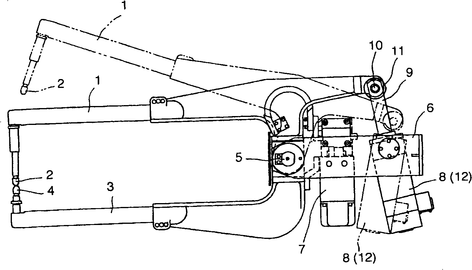
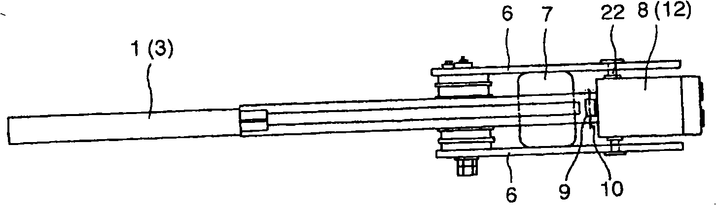
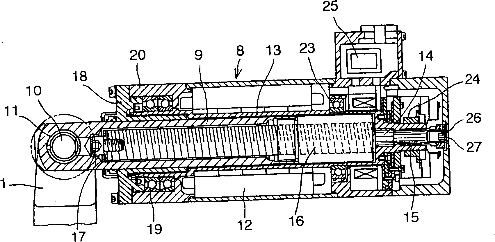
[0020] figure 1 is a side view of an X-type electron gun with an electric drive unit, in which the motor and the pressure applying drive are combined with each other, figure 2 for figure 1 The plan view of the X-type electron gun in, image 3 for as figure 1 A longitudinal section view of the electric drive unit of the main components in, and Figure 4 for image 3 Plan view of the electric drive unit in .

[0021] exist figure 1 with figure 2 Among them, 1 represents a rocker arm, which is an electron gun arm with an electrode 2 at the tip, and 3 is a fixed arm, that is, another electron gun arm with an electrode 4 opposite to the electrode 2 at the tip.

[0022] The middle part of the rocker arm 1 is pivotally supported by the tip end of the gun bracket 6 (which is connected by a pivot 5 to a not shown robot wr...

no. 2 example

[0036] Now refer to the attached Figure 5 with Image 6 , describing an electric drive unit for an X-gun according to a second embodiment of the invention.

[0037] Figure 5 is a schematic side view of an X-type electron gun with an electric drive unit, in which a pressure-applying drive body and a motor are combined with each other; and, Image 6 for Figure 5 Plan view of the X-type electron gun.

[0038] In the second embodiment, the structure of the electric drive unit in which the drive body and the motor are combined with each other due to the application of pressure and image 3 , 4 The first embodiment shown is substantially the same, its parts are denoted by the same reference numerals, and its explanation is omitted.

[0039] exist Figure 5 with Image 6 Among them, the rear end side 3' of the fixed arm 3 extends backward inside the gun bracket 6, and the end of the rear end side 3' passes through the pivots 22, 22 (which are controlled by the housing 20 l...

no. 3 example

[0042] In the first and second embodiments, such as image 3 with Figure 4 As shown, a manual operation hole 27 is located in the cover housing 8' towards a square or pentagonal processing member 26 formed at the rear end of the screw shaft 14 to form the rear end portion of the pressure applying drive body 8.

[0043] In the case where the manual operation hole 27 is provided, when the opening and closing operation of the gun arm cannot be accomplished because the pressure applying shaft 9 cannot be moved due to a failure of the power supply or the electric motor 12, etc., a tool is inserted through the manual operation hole 27, thereby The processing part 26 is rotated so that the screw shaft 14 is rotated by the rotational force of the processing part 26, and the electron gun arm is opened and closed to easily move the electron gun arm to a desired position, thereby obtaining an electric drive for the X-gun which is convenient for maintenance unit.

[0044] The square or...


PUM


Abstract

There is provided an electric driving unit for X-type gun made up by combining a pressure application driving body (8) with a motor (12), wherein the electric driving unit is attached to a fixed arm (3) or a gun bracket (6) utilizing a housing of the motor (12), thereby obtaining the electric driving unit for X-type gun capable of rendering the electric driving unit to be compact and held stably, and causing the maintenance thereof to be executed with reliability and ease.; The electric driving unit for X-type gun, wherein the pressure application driving body (8) and a motor (12) are combined with each other, comprises: a rotary shaft (13) provided in the motor (12) and formed of a hollow shaft to which a screw shaft (14) is secured; a guide bearing (18) provided at the front end side of the motor (12) for guiding the pressure application shaft (9); said pressure application shaft (9) having a part to be driven by the motor (12) and pulled into the motor (12); a hollow part (17) for containing therein a tip end side of the screw shaft (14); a nut (16) to be threaded with the screw shaft (14); and a bearing (11) provided at the front thereof for causing the rear end of the swing arm (1) to be journalled to the pressure application shaft (9) by a pivotal shaft (10); ; said electric driving unit for X-type gun still further comprising a housing (20) provided at the front end of the motor (12); a bearing (19) provided in the housing (20) for bearing a load applied to the rotary shaft (13) of the motor (12) in the axial direction thereof; and a bearing (21) provided in the housing (20) for causing the housing (20) to be journalled to the fixed arm (3) or causing the housing (20) to be journalled to the gun bracket (6) by a pivotal shaft (22).

Description

technical field [0001] The invention relates to an electric drive unit for an X-type gun, comprising two gun arms provided with electrodes at their tips opposite each other, wherein as the middle of the rocker arm of one of the gun arms The part is pivotally connected (journalled) to the gun bracket by a pivot, while the rear end of the rocker arm is connected to the pressure application shaft located in the pressure application drive body, and the rear end of the fixed arm as another gun arm is fixed to the pressure application Drive body or gun mount. Background technique [0002] There is already such an electric drive unit for X-type guns, which comprises two gun arms provided with electrodes at the tips opposite to each other, wherein as the rocker arm of one of the gun arms The middle part is pivotally connected to the gun bracket by a pivot, while the rear end of the rocker arm is connected to the pressure applying shaft located in the pressure applying drive body, a...

Claims


Application Information

Patent Timeline
Patent Type & Authority Applications(China)
IPC IPC(8): B23K11/11
CPCB23K11/314B23K11/11B23K11/24B23K11/36B23K11/002
Inventor 佐藤良夫
Owner OHARA
Why Eureka
Try Eureka