Method for normalizing a printhead assembly

A printer head, standardized value technology, applied in the direction of printing device, printing, etc., can solve the problems of stripe defects, color change and hue shift, and inaccurate reproduction of images, etc.

Active Publication Date: 2008-11-05
XEROX CORP
View PDF0 Cites 2 Cited by
  • Summary
  • Abstract
  • Description
  • Claims
  • Application Information

AI Technical Summary

Problems solved by technology

However, in multiple printer head systems, the "normalized" drop mass produced can vary from printer head to printer head, resulting in head-to-head banding defects that can cause noticeable color variations and / or hue shifts. and produce an image that does not exactly reproduce the desired color

Method used


Image

  • Method for normalizing a printhead assembly
  • Method for normalizing a printhead assembly
  • Method for normalizing a printhead assembly

Examples


Embodiment Construction

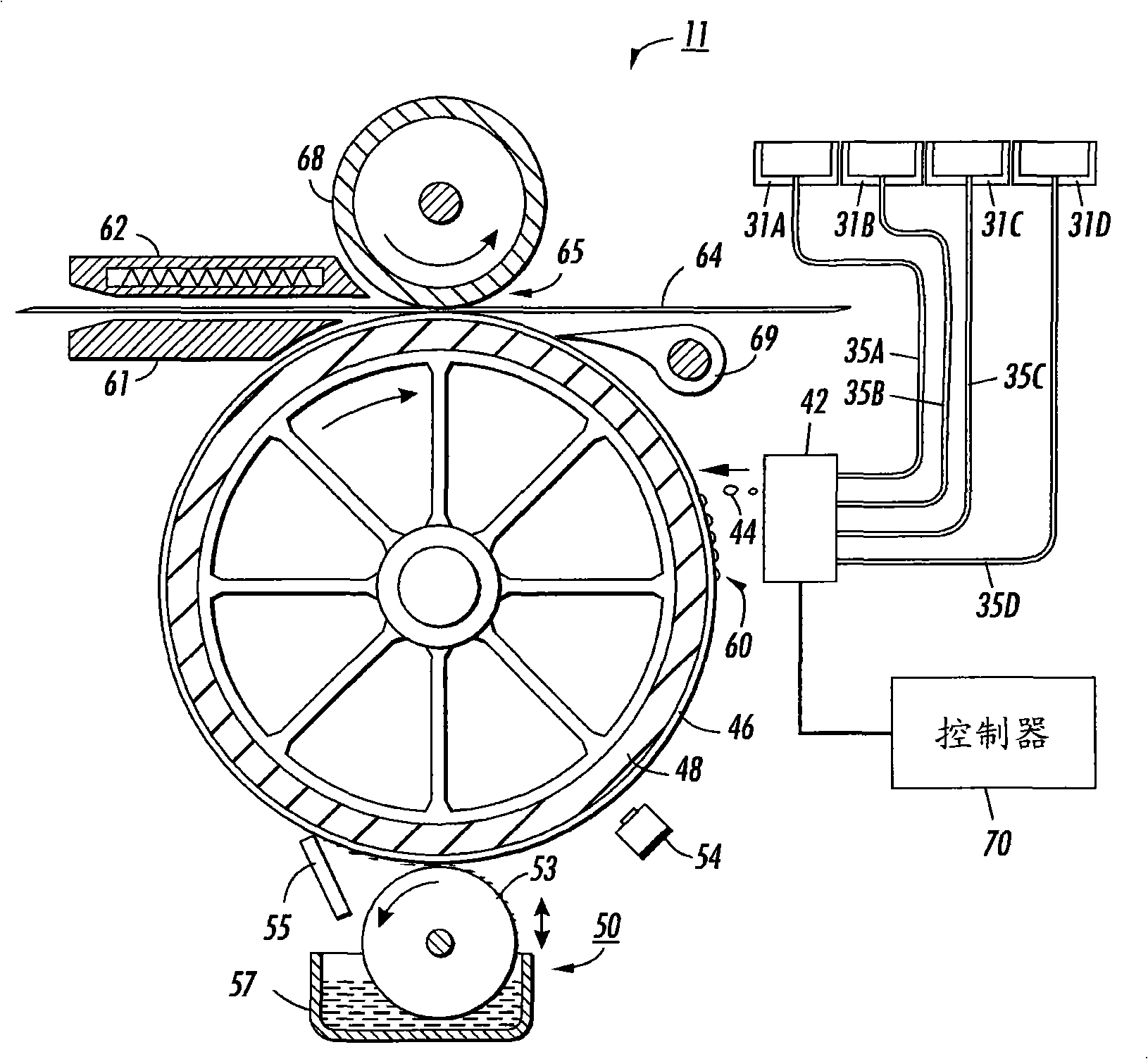
[0049] refer to figure 2 , shows a schematic diagram of the imaging system 11 . For the purposes of this disclosure, an imaging system takes the form of an inkjet printer employing one or more ink drop generators and associated ink supplies. As used herein, a drop generator includes any device capable of ejecting one or more drops of ink. For example, in one embodiment, the drop generator may comprise a printer head including a plurality of inkjets for ejecting ink droplets. Alternatively, the droplet generator may comprise individual inkjets of the printer head.

[0050] figure 2 is a schematic structural diagram of an embodiment of the inkjet printing mechanism 11 . The printing mechanism includes a printer head assembly 42 suitably supported to eject drops 44 of ink onto an intermediate transfer surface 46 that is applied to a support surface of an imaging member 48, which is shown In the form of a drum, but could equally well be in the form of a supported endless belt...


PUM


Abstract

A method of adjusting an ink jet imaging device comprises measuring a drop parameter for drops generated by each drop generator in a plurality of drop generators. Each drop generator is configured to generate a drop in response to a drop generating signal having a fill portion, an eject portion, and a resonance tuning portion. A first portion of the drops are generated by each drop generator at a first fill density, and a second portion of the drops are generated by each drop generator at a second fill density. A drop parameter difference is measured for each drop generator of the plurality of drop generators of drops generated at the first and second fill densities. The resonance tuning portion of the drop generating signal for at least one drop generator is adjusted so that the drop parameter difference for the drop generator corresponds to the drop parameter difference normalization value.

Description

technical field [0001] The present disclosure relates generally to imaging devices that eject ink from an inkjet onto a print drum to form an image that is transferred to a media sheet, and more particularly to imaging devices that use phase change inks. Background technique [0002] In general, inkjet images are formed by selective placement of ink drops ejected from a plurality of drop generators implemented in a printer head or a printer head assembly on a receiver surface. For example, the printer head assembly and receiver surface are moved relative to each other, and the drop generator is controlled, eg by a suitable controller, to eject the drops at the appropriate times. The receiver surface may be a transfer surface or a print medium such as paper. In the case of a transfer surface, the image printed thereon is subsequently transferred to an output print medium, such as paper. Some inkjet printer heads use solid ink that melts. [0003] Inkjet printers can produc...

Claims


Application Information

Patent Timeline
Patent Type & Authority Applications(China)
IPC IPC(8): B41J2/04B41J2/07B41J2/01
CPCB41J2/0057B41J29/393B41J2/01B41J29/38
Inventor B·威廉斯T·L·斯蒂芬斯M·H·迪克松
Owner XEROX CORP
Why Eureka
Try Eureka