
Method and apparatus for encapsulating a ring-shaped member

a ring-shaped member and encapsulation technology, applied in the direction of ceramic shaping apparatus, manufacturing tools, moulds, etc., can solve the problems of affecting the quality of the encapsulated ring, and affecting the encapsulation effect of the ring-shaped member

Inactive Publication Date: 2001-06-19
PANZER TOOL WORKS +1
View PDF19 Cites 19 Cited by
  • Summary
  • Abstract
  • Description
  • Claims
  • Application Information

AI Technical Summary

Benefits of technology

It is one object of this invention to provide a method for annealing or heat treating on encapsulated ring-shaped member to stress relieve the ring-shaped member.
It is another object of this invention to provide a method and apparatus for precisely reproducing a particular size and shape of a casing used to encapsulate a ring-shaped member.
In one preferred embodiment according to this invention, the encapsulated ring-shaped member can then be annealed or heat treated, for example, to a temperature that is sufficient to anneal and thus stress-relieve any undesirable tension within the ring-shaped member. Undesirable tension may be caused by the injection molding method of this invention.
With the method and apparatus according to this invention, the mandrel can be moved with respect to the ring-shaped member, such as a wound coil, without friction or shear forces distorting the shape of the wound coil. Also, with the method and apparatus according to this invention, the encased wound coil can be stress-relieved with a heat treating or an annealing step.

Problems solved by technology

However, the wall thickness of the coating can significantly differ because of manufacturing inconsistencies associated with different variables, such as materials and gravity effects.
Inconsistent casing thicknesses can result in inaccurate toroidal windings.
Because tension is applied to a toroidal wire during a winding process, a sharp casing edge can sever and thus break the toroidal wire during the winding process.

Method used


Image

  • Method and apparatus for encapsulating a ring-shaped member
  • Method and apparatus for encapsulating a ring-shaped member
  • Method and apparatus for encapsulating a ring-shaped member

Examples


Embodiment Construction

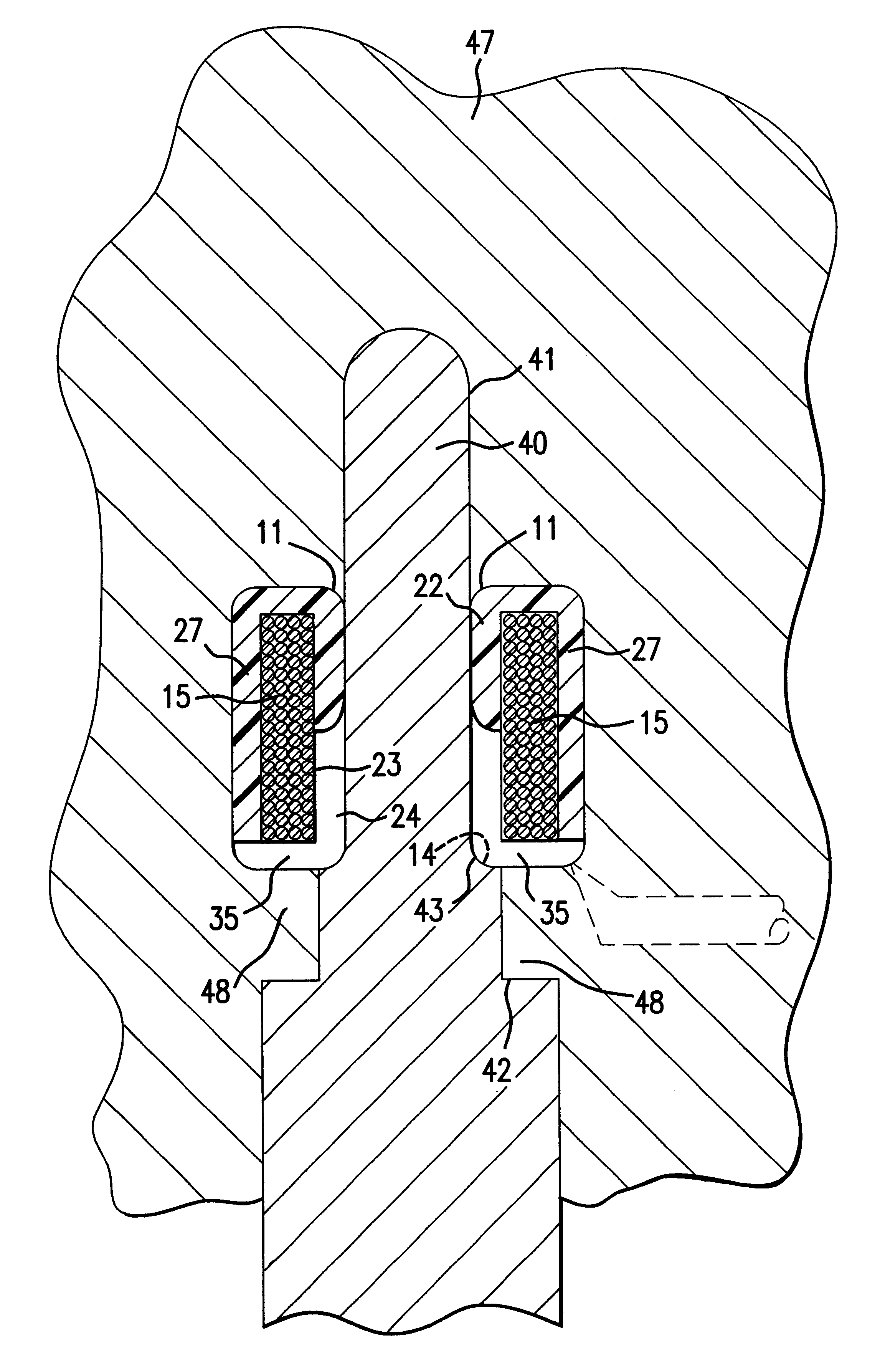
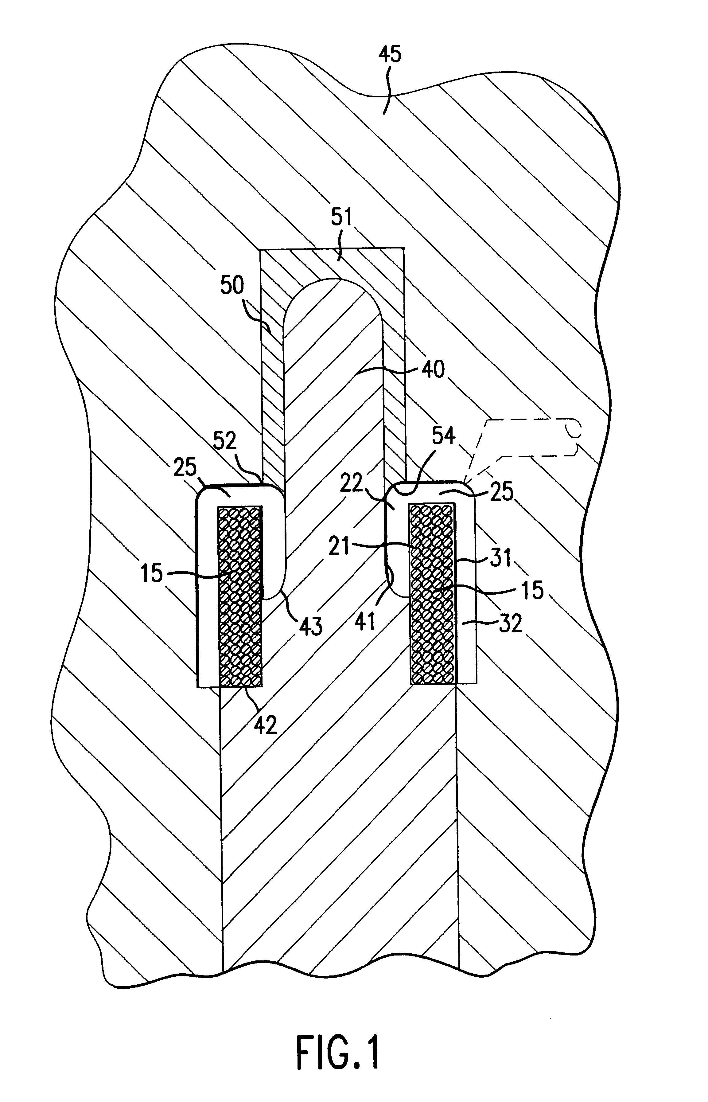
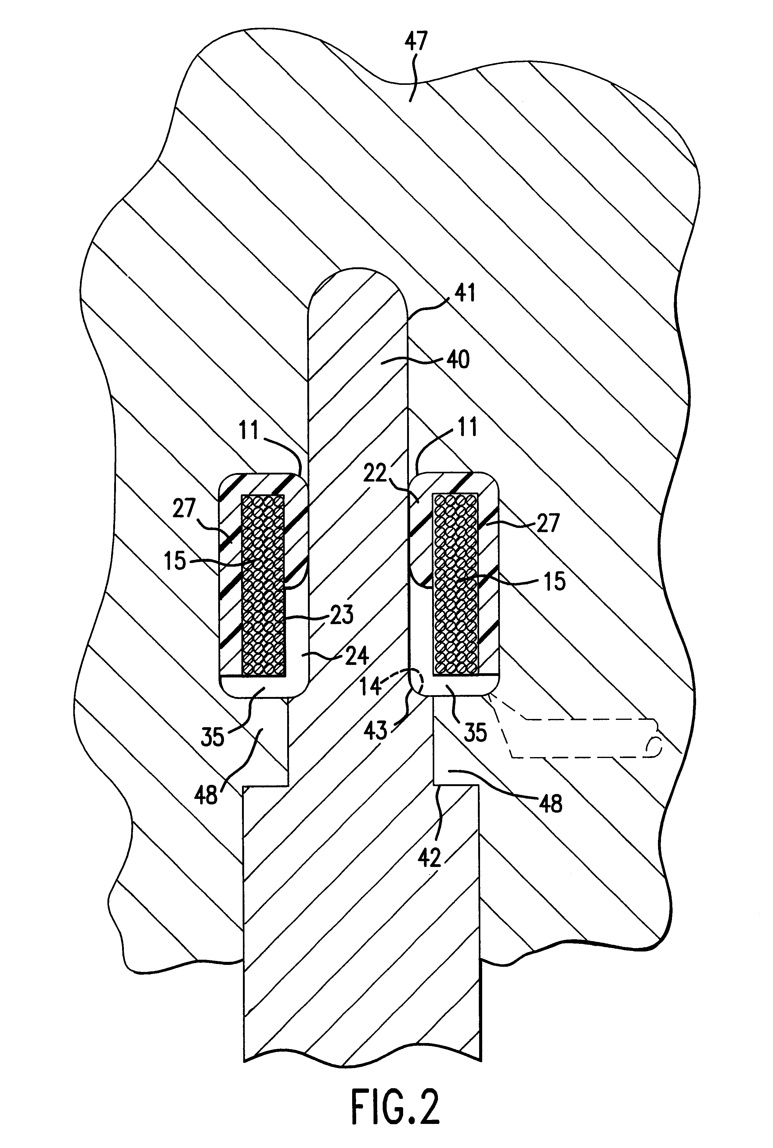
FIGS. 1 and 2 show cross-sectional views of two different injection molding method steps, according to one preferred embodiment of this invention. FIG. 2A shows a cross-sectional view of a second molding step, according to another preferred embodiment of this invention. FIG. 3 shows a perspective view of casing 10 which encapsulates ring-shaped member 15, according to one preferred embodiment of this invention. The method and apparatus of this invention result in casing 10 having rounded edges where two walls of casing 10 meet. As shown in FIG. 3, casing 10 forms inner rounded edge 11 and outer rounded edges 12, 13. Depending upon the particular cross-sectional shape of ring-shaped member 15 and thus casing 10, casing 10 can have more or less than four rounded edges. The embodiment shown in FIGS. 1-3 has four rounded edges 11-14, three of which are shown in FIG. 3.

Ring-shaped member 15 may comprise a solid or rigid ring with any suitable cross-sectional shape, such as shown in FIGS....


PUM

PropertyMeasurementUnit
Stress optical coefficientaaaaaaaaaa
Thermoplasticityaaaaaaaaaa
Tensionaaaaaaaaaa

Abstract

A method and apparatus for encapsulating a ring-shaped member, such as a wound coil of wire, a wound metal ribbon, or a metal composite material. The ring-shaped member is mounted upon a mandrel. The mandrel and the mounted ring-shaped member are positioned in a first mold. A thermoplastic material is injection molded peripherally about a first inner void between the mandrel and the ring-shaped member and a first outer void between the first mold and the ring-shaped member. The mandrel is moved with respect to the ring-shaped member. The mandrel and the re-mounted ring-shaped member are positioned in a second mold. The thermoplastic material is injection molded into a second inner void between the mandrel and the ring-shaped member and within a second outer void between the second mold and the ring-shaped member. The second fill of the thermoplastic material joins with the first fill to fully encapsulate the ring-shaped member. The encapsulated ring-shaped member can then be annealed or heat treated to stress relieve any undesired stress or tension within the ring-shaped member.

Description

1. Field of the InventionThis invention relates to a method and apparatus for encapsulating a ring-shaped member, such as a wound coil of wire, with a casing having a relatively constant thickness and rounded edges, and wherein the encapsulated ring-shaped member is stress-relieved.1. Description of Prior ArtConventional methods have been used to encapsulate ring-shaped members, such as wound coils of wire. For example, wound coils have been dipped in an epoxy material or an enamel material. The dipping process results in a coated or encapsulated wound coil. However, the wall thickness of the coating can significantly differ because of manufacturing inconsistencies associated with different variables, such as materials and gravity effects.In other conventional methods, a wound coil is encased by positioning the wound coil within a prefabricated casing or housing having two or more pieces. The multiple casing or housing pieces are then welded, adhered or otherwise sealed or mechanica...

Claims


Application Information

Patent Timeline
IPC IPC(8): B29C45/16B29C71/02
CPCB29C45/1635B29C45/1671B29C71/02B29C2071/022
Inventor WALSH, EDWARD BRIAN
Owner PANZER TOOL WORKS
Learn More