Electrobath structure

An electrolytic cell and cell body technology, applied in the field of electrolytic cell structure, can solve problems such as high economic cost and complex structure, and achieve the effects of safe and simple operation, reduced transportation cost, and convenient modification.

Active Publication Date: 2008-11-05
FUJIAN NANPING ALUMINUM
View PDF1 Cites 0 Cited by
  • Summary
  • Abstract
  • Description
  • Claims
  • Application Information

AI Technical Summary

Problems solved by technology

The above structure can make the lifting center of the upper structure of the electrolytic cell coincide with the center of gravity of the upper structure of the electrolytic

Method used


Image

  • Electrobath structure
  • Electrobath structure
  • Electrobath structure

Examples


Example Embodiment

[0023] Hereinafter, the present invention will be further described in detail with reference to the accompanying drawings and embodiments.
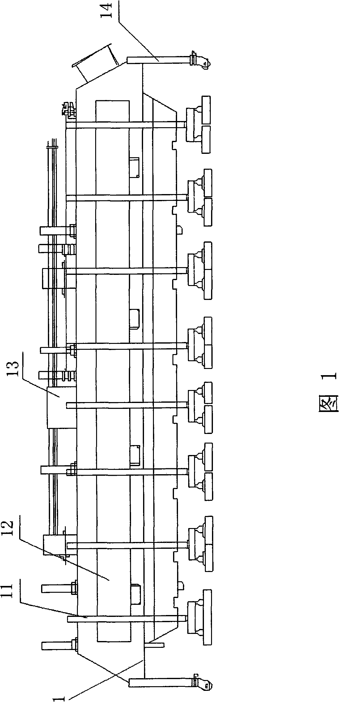
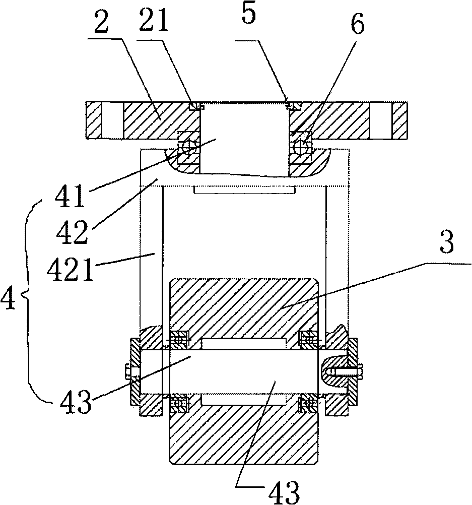
[0024] Refer to Figure 1 to image 3 An electrolytic cell structure of the present invention includes a cell body and an upper electrolytic cell 1. The upper electrolytic cell 1 includes an anode rod 11, a bus bar 12, a feeding mechanism 13 and four supporting feet 14, and the bottom of each supporting leg 14 is respectively fixed A supporting plate 2 is provided, and a rotating wheel 3 is fixed on the supporting plate 2 through a bracket mechanism 4.

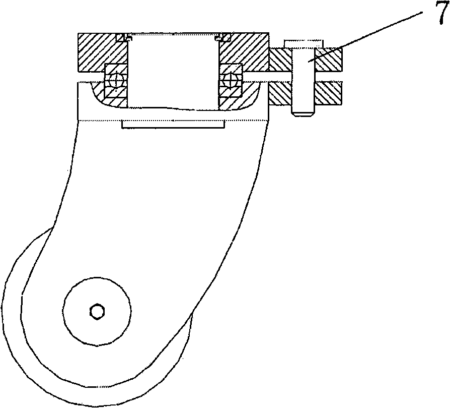
[0025] In actual use, the support plate 2 adopts a 60mm thick steel plate, which is fixed to the support foot 14 by a screw. The rotating wheel 3 is sleeved on the bracket shaft 43 and fixed between the two side plates 421 of the bracket body 42.

[0026] The support shaft 41 connects the support body 42 and the support plate 2, and passes through the support plate 2, and is fixed in the sleeve...


PUM


Abstract

The invention discloses an electrolysis slot structure and comprises a slot body and an upper part of electrolysis slot, and the upper part of electrolysis slot comprises an anode rod, a bus, a material feeding mechanism and four supporting feet, wherein, a facing bar is respectively and fixedly arranged under each supporting foot, and a rotating wheel is fixed on the facing bar through a bracket mechanism. The bracket mechanism comprises a supporting shaft, a bracket body and a bracket shaft, the supporting shaft is connected with the bracket body and the facing bar, runs through the facing bar, and is sleeved inside a trepan boring that is arranged on an upper end face of the facing bar through a cutting ferrule; the bracket body takes a shape of a doorframe, and the rotating wheel is arranged between two lateral boards and fixed on the bracket body through the bracket shaft. The electrolysis slot structure has the advantages that an original structure can be conveniently remodeled, and the present electrolysis slot structure can greatly lower transportation cost during the transportation of heavy repair and has safe, simple and easy operations.

Description

technical field [0001] The invention relates to an electrolytic cell structure, in particular to an electrolytic cell structure which can greatly reduce the overhaul cost of the electrolytic cell and shorten the maintenance time. Background technique [0002] Usually the design life of the electrolyzer is 5-6 years, therefore, the structure of the electrolyzer needs to be overhauled every 5 years before it can be used normally. The maintenance of the electrolyzer is divided into two parts, one is: the maintenance of the electrolyzer shell, and the other is: the maintenance of the upper part of the electrolyzer. The maintenance of the tank shell can prolong the working life of the electrolytic cell through the improvement of the structural design, the selection of the lining material, the strengthening of management in the later work, and the timely detection of the damaged parts and early maintenance. [0003] The maintenance of the upper part of the electrolytic cell is ma...

Claims


Application Information

Patent Timeline
IPC IPC(8): C25C3/08
Inventor 王福发
Owner FUJIAN NANPING ALUMINUM
Why Eureka
Try Eureka