Back light module unit and optical panel thereof

一种光学板、光源的技术,应用在光学、光学元件、非线性光学等方向,能够解决背光模组100出光不均等问题

Inactive Publication Date: 2008-11-05
HONG FU JIN PRECISION IND (SHENZHEN) CO LTD +1
View PDF0 Cites 4 Cited by
  • Summary
  • Abstract
  • Description
  • Claims
  • Application Information

AI Technical Summary

Problems solved by technology

The matching design of the light-emitting diode 105 and the reflector 106 can reduce the bright area directly above the light-emitting diode 105 to a certain extent, but the backlight module 100 still has the disadvantage of uneven light output

Method used


Image

  • Back light module unit and optical panel thereof
  • Back light module unit and optical panel thereof
  • Back light module unit and optical panel thereof

Examples


Embodiment Construction

[0018] The backlight module and its optical board of the present invention will be further described in detail below with reference to the drawings and embodiments.

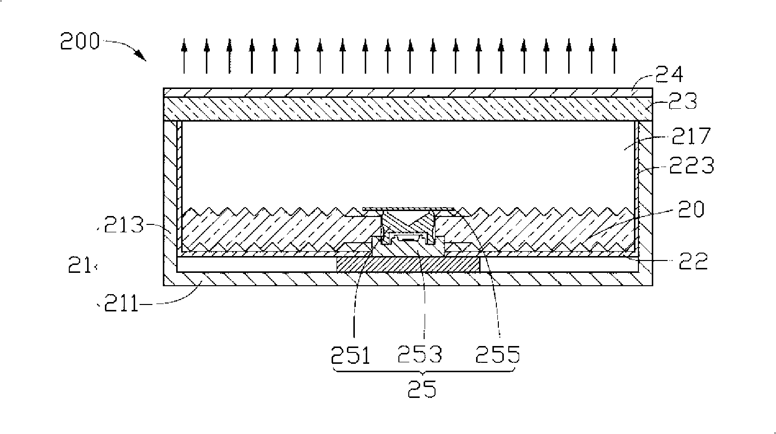
[0019] See figure 2 , shows the backlight module 200 of the preferred embodiment 1 of the present invention, which includes a frame 21 , a reflector 22 , a diffuser 23 , an edge-type point light source 25 , and an optical plate 20 . The frame 21 includes a rectangular bottom plate 211 and four sidewalls 213 vertically extending from the edge of the bottom plate 211 to the same side thereof and connected to each other. The four side walls 213 and the bottom plate 211 together form a cavity 217 . The diffuser plate 23 is disposed on top of the plurality of sidewalls 213 for covering the cavity 217 . The cavity 217 is used for accommodating components such as the point light source 25 , the reflecting plate 22 and the optical plate 20 . The light emitted from the point light source 25 is fully mixed in the cavit...


PUM


Abstract

An optical board comprises at least one optical board unit which comprises a light emitting surface and a base surface opposite to the light emitting surface. The light emitting surface and the base surface are respectively formed with a plurality of micro-projections. Each micro-projection comprises at least three side surfaces connected with one another. The horizontal width of each side surface reduces along the direction away from the base surface of the micro-projection. The base surface is provided with at least one light source accommodation part. The invention also provides a backlight module which adopts the optical board and has the advantage of homogeneous light emission.

Description

technical field [0001] The invention relates to a backlight module and its optical board, in particular to a backlight module for liquid crystal display and its optical board. Background technique [0002] Since the liquid crystal itself of the liquid crystal display panel does not have light-emitting properties, it is necessary to provide a light source device, such as a backlight module, for the liquid crystal display panel in order to achieve a display effect. The function of the backlight module is to supply a surface light source with sufficient brightness and uniform distribution to the LCD panel. [0003] See figure 1 , shows a conventional backlight module 100 , which includes a frame 101 , a reflector 102 , a diffuser 103 , a prism sheet 104 and at least one LED 105 . The frame 101 includes a bottom plate 1011 and a plurality of sidewalls 1013 vertically extending from the edge of the bottom plate 1011 to the same side thereof. The bottom plate 1011 and the plura...

Claims


Application Information

Patent Timeline
Patent Type & Authority Applications(China)
IPC IPC(8): G02F1/13357G02B6/00G02F1/1335
CPCG02B6/0021G02B6/0031G02B6/0036G02B6/0038G02B6/0078G02F1/133603G02F1/133611G02F2001/133607G02F1/133607
Inventor 章绍汉
Owner HONG FU JIN PRECISION IND (SHENZHEN) CO LTD
Why Eureka
Try Eureka