
Clock switch circuit

A clock switching and circuit technology, applied in the direction of electrical components, pulse processing, signal generation/distribution, etc., can solve problems such as glitches, application circuit errors, unpredictable circuits, etc., and achieve the effect of avoiding glitches and metastable states

Inactive Publication Date: 2008-11-05
INVENGO INFORMATION TECH
View PDF0 Cites 41 Cited by
  • Summary
  • Abstract
  • Description
  • Claims
  • Application Information

AI Technical Summary

Problems solved by technology

The clock switching circuit in the prior art has the following deficiencies: 1. A burr will be generated during clock switching, and the burr may cause subsequent flip-flops to act on the burr, which will lead to the occurrence of erroneous actions and eventually lead to functional errors; 2. The generation of metastable state. Some clock switching circuits use feedback to connect the output of a clock flip-flop to the input of another clock flip-flop. Due to the asynchronous relationship between clocks, it is likely to cause a metastable state. generation, thus making the circuit in an unpredictable state
The above problems will cause the application circuit to go wrong

Method used


Image

  • Clock switch circuit
  • Clock switch circuit

Examples


Embodiment Construction

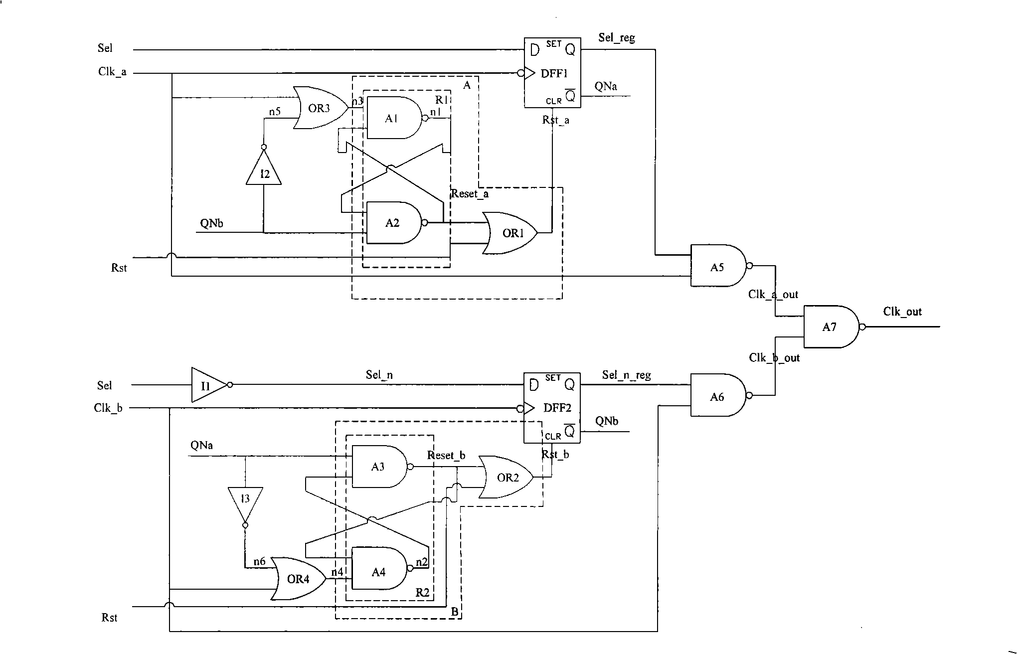
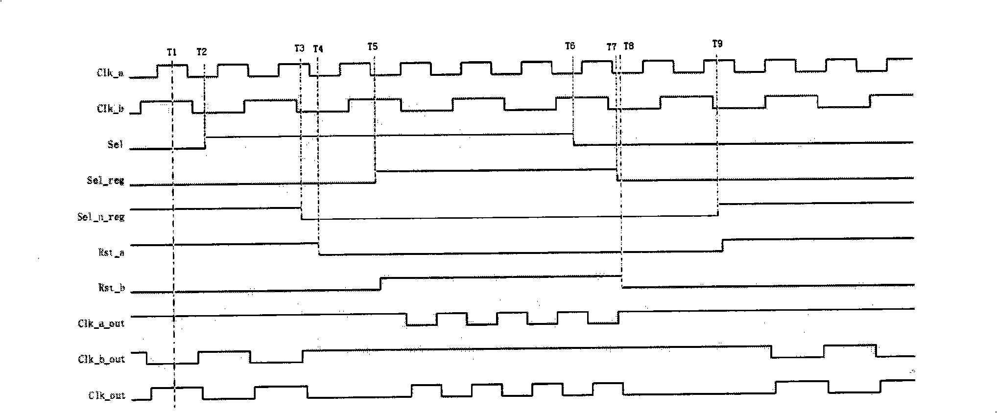
[0014] The present invention will be described in further detail below in conjunction with the accompanying drawings and embodiments. The clock switching circuit of the present invention adopts an asynchronous reset method to synchronize the clock selection signal and the clock signal, switches between the irrelevant first clock signal Clk_a and the second clock signal Clk_b according to the selection signal Sel, and outputs a glitch-free clock Output signal Clk_out, and avoid metastability problem.

[0015] The clock switching circuit of the present invention is composed of two reset generating circuits, two OR gates, three NOT gates, two D flip-flops and a clock output circuit. Such as figure 1 As shown, the first reset generating circuit A and the second reset generating circuit B are respectively connected to the first D flip-flop DFF1 and the second D flip-flop DFF2, the two D flip-flops are triggered by the falling edge of the clock and have an asynchronous reset termin...


PUM


Abstract

The invention discloses a clock commutation circuit, which resolves technical problem of producing bur and metastable state. The clock commutation circuit of the invention is composed of two reset producing circuits, two OR gates, three NOT gates, two D-flip-flops and a clock output circuit, the reset producing circuits and the NOT gates constitutes a RS latch. Compared with the prior technology, when the first clock is switched to the second clock, the gating signal of the first clock is switched off when the first clock is at a low level, meanwhile the reset outputting signal of the second RS latch is released, the gating signal of the second clock is switched-on when the second clock is at a low level, thereby avoiding the bur during the clock switch. The reset producing circuit ensures that the asynchronous reset terminal of the D-flip-flop executes the synchronization operation to the reset signal through the RS latch circuit when the clock is at a low level, thereby avoiding the production of metastable state.

Description

technical field [0001] The invention relates to a clock circuit, in particular to a circuit for converting two clock signals. Background technique [0002] At present, many circuit applications need to switch the clock frequency. For example, different clock frequencies are required for receiving data and returning data during data communication, which requires switching between clocks of different frequencies. The clock switching circuit in the prior art has the following deficiencies: 1. A burr will be generated during clock switching, and the burr may cause subsequent flip-flops to act on the burr, which will lead to the occurrence of erroneous actions and eventually lead to functional errors; 2. The generation of metastable state. Some clock switching circuits use feedback to connect the output of a clock flip-flop to the input of another clock flip-flop. Due to the asynchronous relationship between clocks, it is likely to cause a metastable state. The generation, so th...

Claims


Application Information

Patent Timeline
IPC IPC(8): G06F1/08H03K5/1252
Inventor 游昊杰熊立志傅霖煌王振华武岳山
Owner INVENGO INFORMATION TECH
Learn More