Clock switching circuit of gigabit Ethernet transceiver

A Gigabit Ethernet and clock switching technology, which is applied in the field of clock switching circuits, can solve the problems that Gigabit Ethernet circuit functions cannot generate output clocks, do not support skip clock switching, output clock glitches, etc., so as to avoid glitches And the generation of metastable state, smooth switching, and the effect of ensuring correctness

Active Publication Date: 2020-06-19
XIAN MICROELECTRONICS TECH INST
View PDF9 Cites 0 Cited by
  • Summary
  • Abstract
  • Description
  • Claims
  • Application Information

AI Technical Summary

Problems solved by technology

However, choosing different transceivers and different communication rates involves dynamic switching of clocks across clock domains, and the three switching clocks and control signals come from different clock domains. How to achieve correct switching of clocks across clock domains while avoiding metastability or generating clock glitches is a critical issue that needs to be addressed
[0003] The prior art generally selects the MUX selection circuit, and this method is generally used in circuits that do not have strict requirements on the clock system; however, due to the difference in input clock frequency and phase, As well as the asynchronous switching signal and clock, it is easy to cause glitches in the output clock during the switching process
[0004] The patent document "A glitch-free switching circuit supporting N clocks (CN201610008589.9)" discloses a clock switching scheme, but the number N of clocks to b

Method used


Image

  • Clock switching circuit of gigabit Ethernet transceiver
  • Clock switching circuit of gigabit Ethernet transceiver
  • Clock switching circuit of gigabit Ethernet transceiver

Examples


Example Embodiment

[0050] The present invention will be further described in detail below in conjunction with specific embodiments, which are to explain rather than limit the present invention.

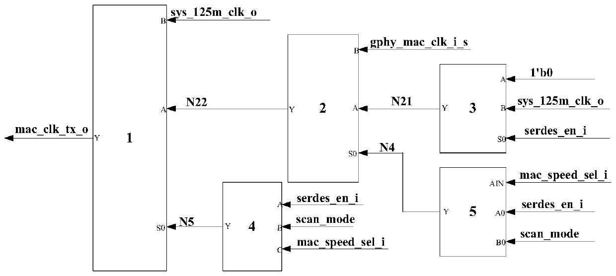
[0051] The clock switching circuit of the Gigabit Ethernet transceiver of the present invention mainly includes MXT2_1-MXT2_3 switching modules, NOR3 three-input or non-modular, OAI2 three-input or NAND module, nandb0 two-input NAND module, inv0-inv5 inversion module, nand0~nand3 two input NAND modules, dffr0~dffr2 reset register module, dffs0~dffs2 set register module.

[0052] Its overall structure diagram is as follows figure 1 shown, the details are as follows:

[0053] 1. The main function of the MXT2_1 switching module (label 1) is to realize the clock switching between the transceiver serdes and gphy working at 1000M, and its logical expression is Y=((~S0)·A+S0·B); in the default mode Output the clock sys_125m_clk_o at the B end, which is the 125MHz working clock of the system. The switching pr...


PUM


Abstract

The invention provides a clock switching circuit of a gigabit Ethernet transceiver. According to the circuit, smooth switching of different clock domains is achieved through a three-level synchronization and interlocking mechanism, the risk that burrs and metastable states are generated due to clock switching across the clock domains is avoided, the correctness of circuit functions is guaranteed,a correct output clock can be provided during resetting, and the logic function of a chip during resetting is guaranteed.

Description

technical field [0001] The invention belongs to the field of computer communication and network, and relates to a clock switching circuit of a Gigabit Ethernet transceiver, which is especially suitable for the fields of Ethernet controllers, network servers, computer data storage systems and the like. For example, data service centers, large switches, etc. It is suitable for circuit design with high integration and low overhead. Background technique [0002] Gigabit Ethernet supports two transceivers, gphy and serdes, and gphy supports three rates of 10 / 100 / 1000Mbps; when working, users can choose between gphy and serdes according to their needs, and the communication rate of gphy can be 10M, Switch between 100M and 1000M. However, selecting different transceivers and different communication rates involves dynamic switching of clocks across clock domains, and the three switching clocks and control signals come from different clock domains. How to achieve correct switching ...

Claims


Application Information

Patent Timeline
IPC IPC(8): H03K5/1252
CPCH03K5/1252
Inventor 冯海强王剑峰李龙飞刘钊
Owner XIAN MICROELECTRONICS TECH INST
Why Eureka
Try Eureka