Steam turbine cycle

A technology of steam turbines and turbines, applied in steam applications, steam engine devices, machines/engines, etc., to achieve high cycle thermal efficiency

Inactive Publication Date: 2008-11-05
KK TOSHIBA
View PDF0 Cites 5 Cited by
  • Summary
  • Abstract
  • Description
  • Claims
  • Application Information

AI Technical Summary

Problems solved by technology

Especially in recent years, with the advancement of high-temperature materials, the high temperature of steam has been promoted, and the thermal efficiency of

Method used


Image

  • Steam turbine cycle
  • Steam turbine cycle
  • Steam turbine cycle

Examples


no. 1 Embodiment approach

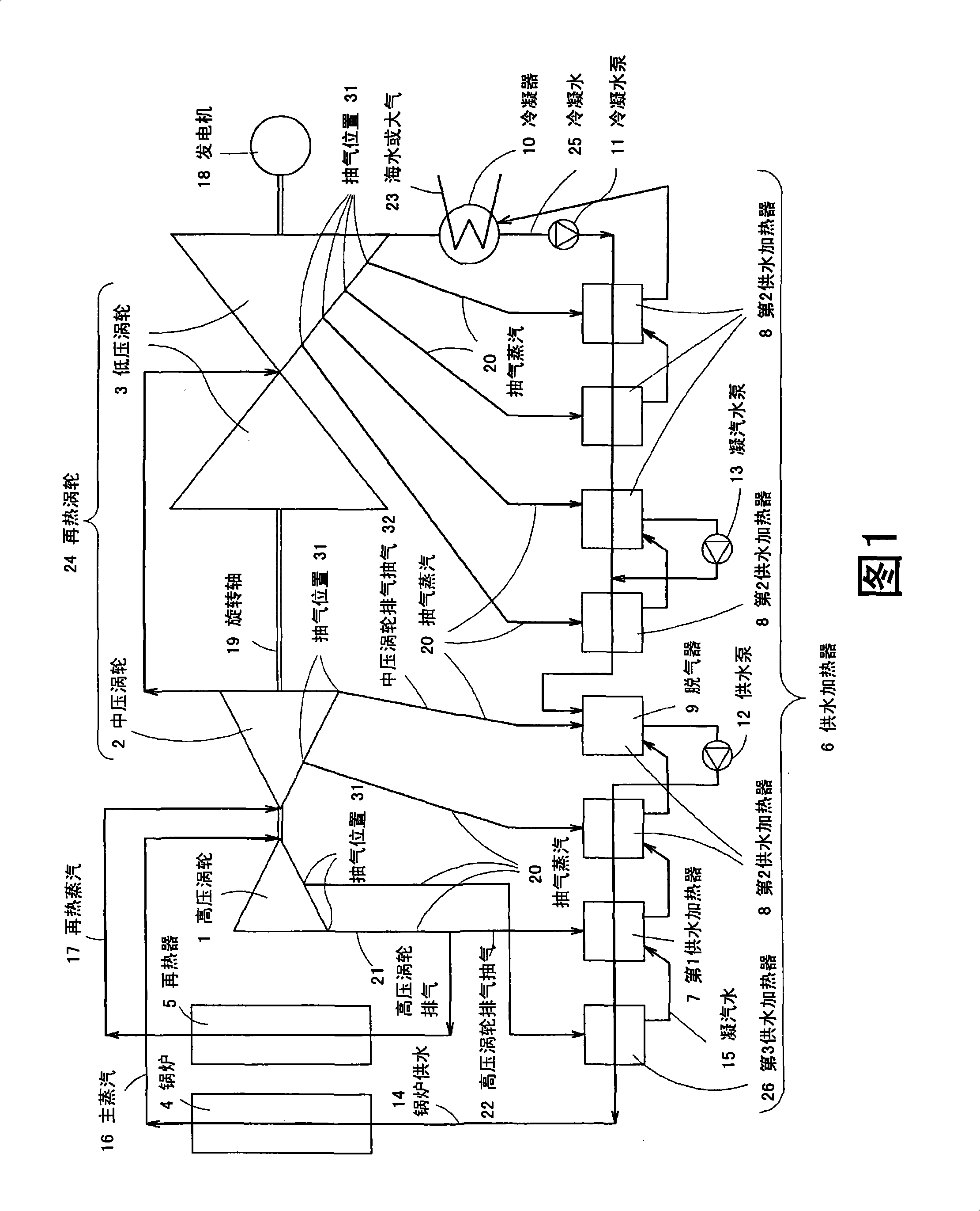
[0029] Hereinafter, a first embodiment of the steam turbine cycle of the present invention will be described with reference to the drawings. Here, FIG. 1 is a diagram showing a first embodiment of the present invention.

[0030] The steam turbine cycle of the present embodiment constitutes a Rankine cycle, the Rankine cycle is a first-stage reheating cycle in which the working fluid is water, and is a regenerative cycle, and has: a high-pressure turbine 1; a reheating turbine 24; a boiler 4; a water supply heater 6. The water supplied to the boiler 4 is heated by the extraction steam from the high-pressure turbine 1 and the reheat turbine 24 ; the water supply pump 12 ; and the condenser 10 .

[0031] And, the temperature of the steam at the outlet of the boiler 4 is above 590° C., and the temperature rise ratio is above 1.9 and below 3.5; The corresponding ratio of the increase in the temperature of the supplied water from the first feed water heater 7 to the increase in the...

no. 2 Embodiment approach

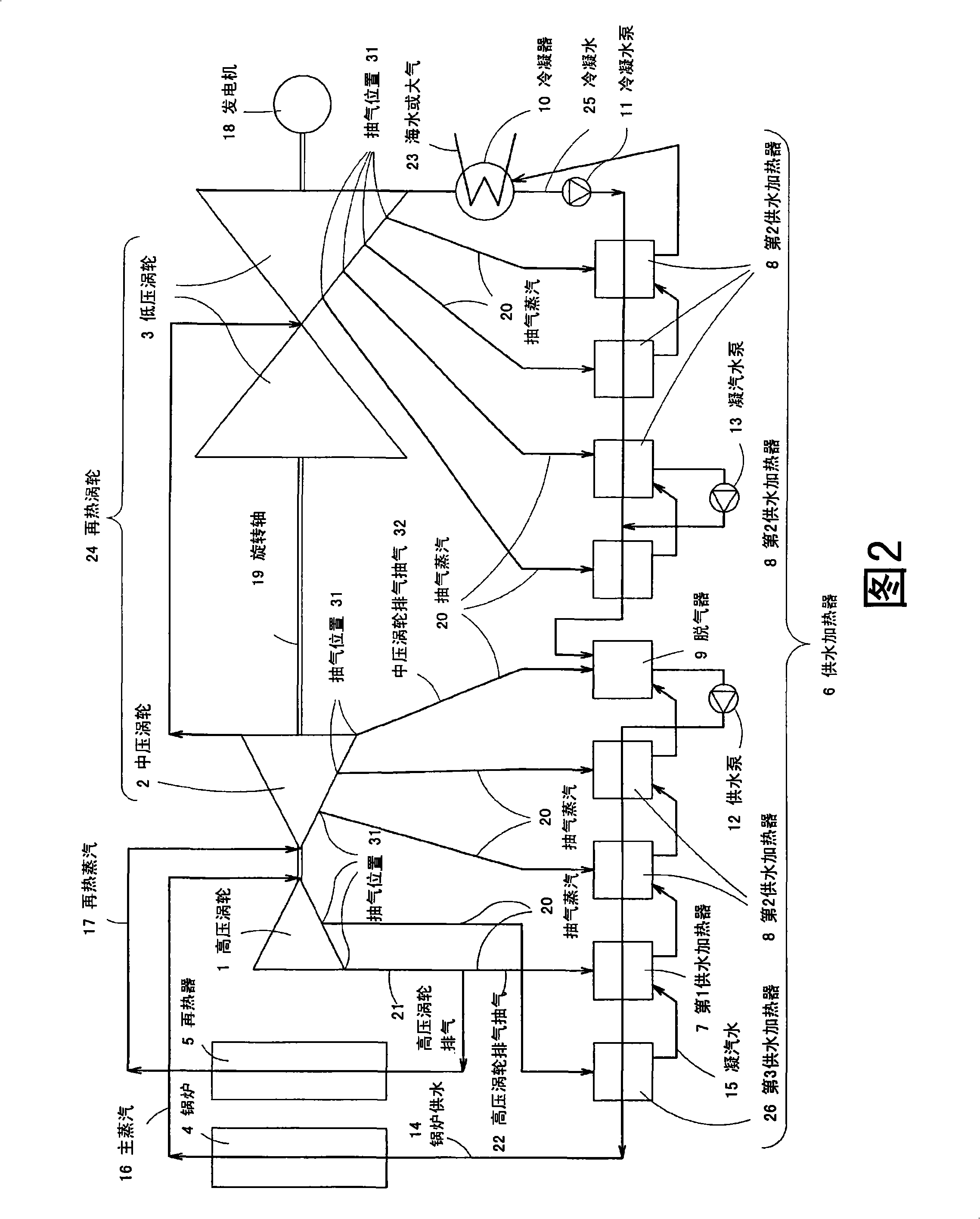
[0043] Next, a second embodiment of the present invention will be described with reference to FIG. 1 .

[0044] The steam turbine cycle of the present embodiment constitutes a Rankine cycle, the Rankine cycle is a first-stage reheating cycle in which the working fluid is water, and is a regenerative cycle, and has: a high-pressure turbine 1; a reheating turbine 24; a boiler 4; a water supply heater 6. The water supplied to the boiler 4 is heated by the extraction steam from the high-pressure turbine 1 and the reheat turbine 24 ; the water supply pump 12 ; and the condenser 10 .

[0045] Moreover, the steam temperature at the outlet of the boiler 4 is above 590° C., and the specific enthalpy increase ratio is above 1.9 and below 3.5; The ratio of the increase in the specific enthalpy of the supplied water to the increase in the average specific enthalpy of the supplied water of the second feed water heater 8 whose water supply pressure is lower than that of the first feed water...

no. 3 Embodiment approach

[0053] Next, a third embodiment of the present invention will be described with reference to FIG. 1 .

[0054] The steam turbine cycle of the present embodiment constitutes a Rankine cycle, the Rankine cycle is a first-stage reheating cycle in which the working fluid is water, and is a regenerative cycle, and has: a high-pressure turbine 1; a reheating turbine 24; a boiler 4; a water supply heater 6. The water supplied to the boiler 4 is heated by the extraction steam from the high-pressure turbine 1 and the reheat turbine 24 ; the water supply pump 12 ; and the condenser 10 .

[0055] Moreover, the steam temperature at the outlet of the boiler 4 is above 590°C, and the temperature rise ratio is above 1.9 and below 3.5; The ratio of rise to the average feed water temperature rise of the feed water heaters other than the first feed water heater 7.

[0056] Here, the water heaters other than the first water heater 7 refer to the second water heater 8 that supplies water at a lo...


PUM


Abstract

The invention provides a steam turbine cycle which comprises a high pressure turbine (1), a reheat turbine (24), a boiler (4), a water supply heater (6) for heating supply water to the boiler (4) with extraction steam from the turbines (1, 24), a water supply pump (12), and a condenser (10), and which is a single-stage reheat cycle where the working fluid is water and Rankine cycle as a regenerative cycle. Steam temperature at the outlet of the boiler (4) is 590 degree centigrade or above. The cycle is constituted such that the temperature rise ratio between supply water temperature rise at a first supply water heater (7) corresponding to extraction steam (high pressure turbine exhaust gas extraction steam) (22) from exhaust gas of the high pressure turbine (1) and an average of supply water temperature rises at a second supply water heater (8) where the pressure of supply water is lower than that of first supply water heater (7) falls within a range of 1.9-3.5.

Description

technical field [0001] The invention relates to a steam turbine cycle with high cycle thermal efficiency. Background technique [0002] As a prior art, a steam turbine cycle used in thermal power plants and the like will be described with reference to FIG. 1 . [0003] In the boiler 4, the boiler feed water 14 is heated by fuel combustion heat, etc., and superheated steam of sufficiently high temperature (hereinafter referred to as main steam 16 ) is generated. Sometimes the superheated steam is a supercritical pressure fluid. [0004] The main steam 16 flows into the high-pressure turbine 1 and flows while expanding, reducing the pressure and temperature. [0005] Most of the high-pressure turbine exhaust gas 21 flowing out of the high-pressure turbine 1 flows into the reheater 5 , becomes higher in temperature, and flows into the intermediate-pressure turbine 2 as reheated steam 17 . [0006] The pressure and temperature of the steam flowing while expanding in the inter...

Claims


Application Information

Patent Timeline
IPC IPC(8): F01K7/40F01K7/34F01K7/38
CPCF01K7/38F01K7/40F01K7/22F01K17/00F01K7/34
Inventor 后藤功一冲田信雄
Owner KK TOSHIBA
Why Eureka
Try Eureka