

Milling machine for processing single screw compressor rotor
Patent Information
- Authority / Receiving Office
- CN · China
- Current Assignee / Owner
- XI AN JIAOTONG UNIV
- Publication Date
- 2008-11-12
- Estimated Expiration
- Not applicable · inactive patent
Smart Images
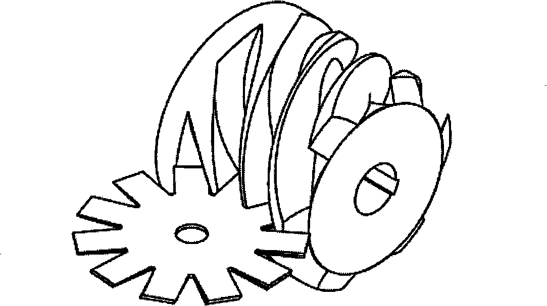
Figure 1 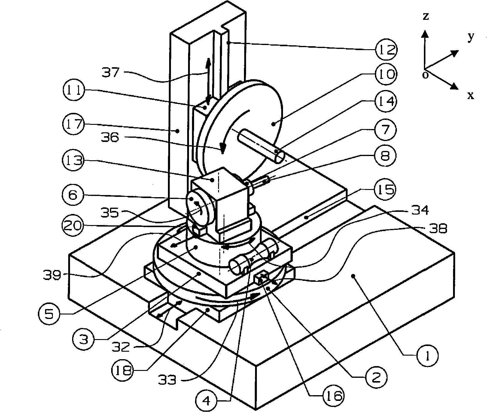
Figure 2 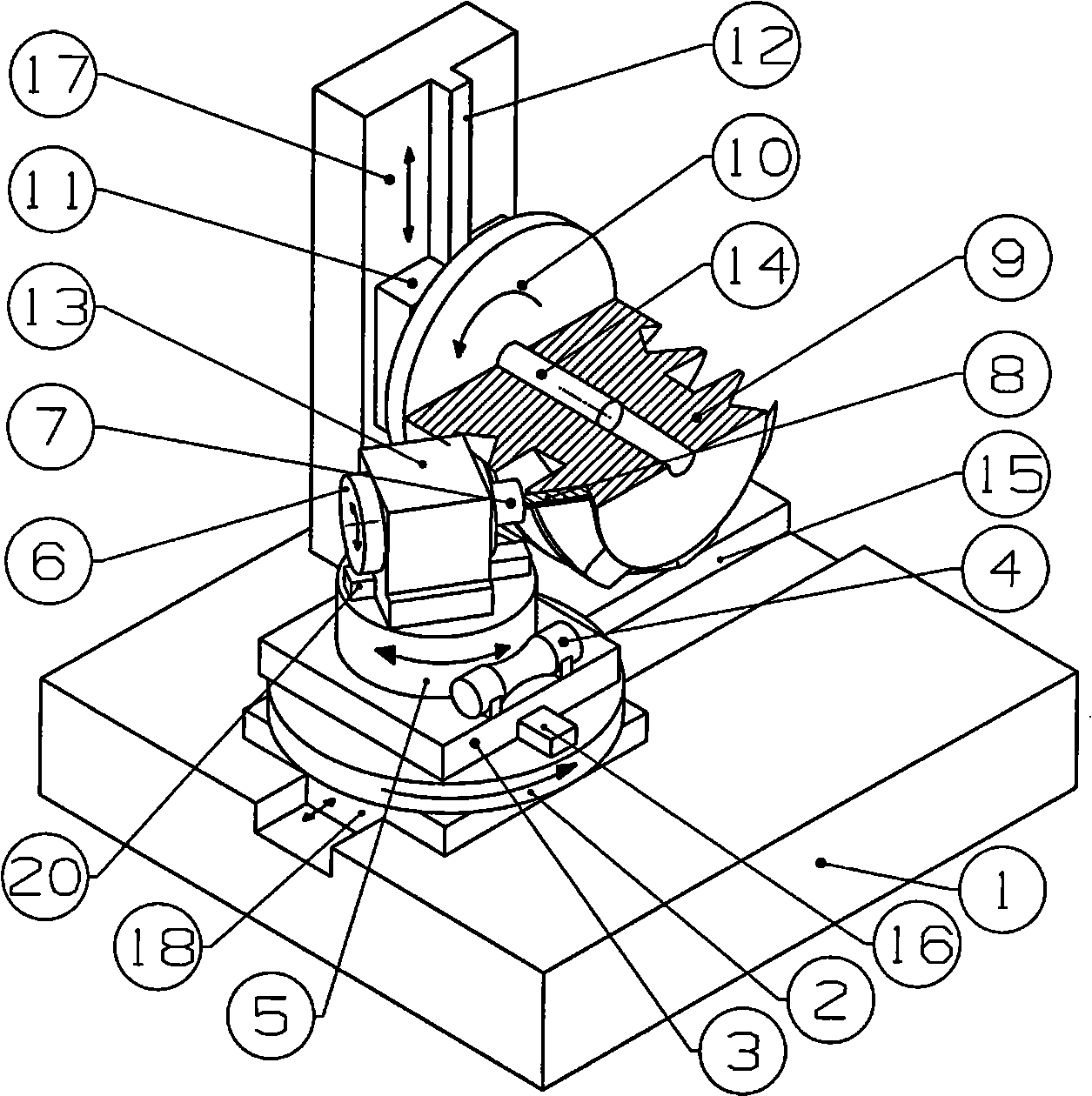
Figure 3
Abstract
Description
technical field
[0001] The invention relates to mechanical processing equipment, in particular to a milling machine for processing screw rotors of single screw compressors. Background technique
[0002] Compressors are widely used in railways, ships, mines, construction, chemicals, textiles, metallurgical machinery, military instruments, ships and other industries. Compared with reciprocating compressors and twin-screw compressors, single-screw compressors have the advantages of simple structure, reliable operation, small size, light weight, and low noise.
[0003] There are more than ten companies in France, Japan, Britain, the United States, the Netherlands and other countries that can produce single-screw compressors abroad. In recent years, some manufacturers in my country have also begun to produce single-screw compressors, but their performance indicators are generally lower than imported products. Especially in the case of using the same material, the service life of...