
Foam maker and control method thereof

A foaming machine and template technology, which is applied to the foaming machine and its control field, can solve the problems of large instantaneous starting current, increased instantaneous current, unfavorable operation, etc., and achieves the improvement of the degree of mechanical automation, the improvement of the utilization rate of electric energy, and the improvement of The effect of utilization efficiency

Inactive Publication Date: 2008-11-12
蔡祥山
View PDF0 Cites 6 Cited by
  • Summary
  • Abstract
  • Description
  • Claims
  • Application Information

AI Technical Summary

Problems solved by technology

However, this automatic foaming machine is usually controlled by a PLC at one station, which cannot achieve high automation
Moreover, due to the foaming process of materials such as polystyrene, it is only necessary to start the motor to drive the oil cylinder during the process of clamping the upper template and the middle template, but considering the energy consumed by starting the motor, other processes (such as high temperature heating) Although the drive of the motor is not required in the process), the motor is still running, which causes a waste of energy
[0005] In addition, there is another situation at present, that is, the motor of the above-mentioned foaming machine only works when the mold is closed
However, since the oil pressure of the oil pump needs a certain period of time to rise to a certain value, the oil pressure when the motor is just started is unstable, which is not conducive to operation and is likely to cause product quality problems.
In addition, the foaming machine that works in this way requires frequent start-up of the motor, which has the following defects: 1) The instantaneous start-up current of the motor is large and consumes power; 2) It interferes with the quality of the power grid and easily interferes with the automatic control machine; 3. ) The instantaneous current increases, and the voltage increases accordingly, which makes the transformer load larger, especially when multiple units are operating at the same time

Method used


Image

  • Foam maker and control method thereof
  • Foam maker and control method thereof
  • Foam maker and control method thereof

Examples


Embodiment Construction

[0037] The embodiments of the present invention will be described in detail below with reference to the accompanying drawings, but the present invention can be implemented in many different ways defined and covered by the claims. The same components are denoted by the same reference numerals in the drawings.

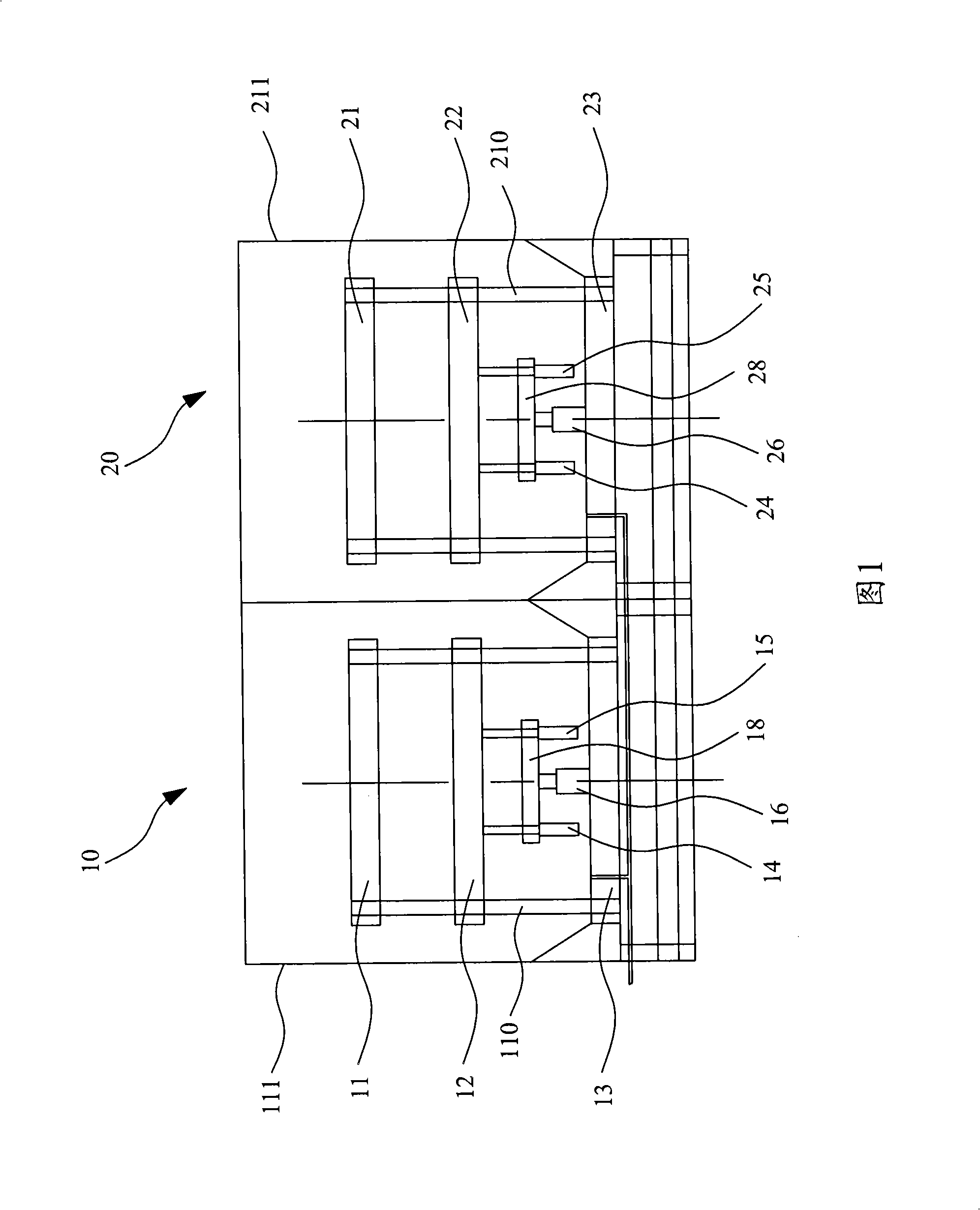
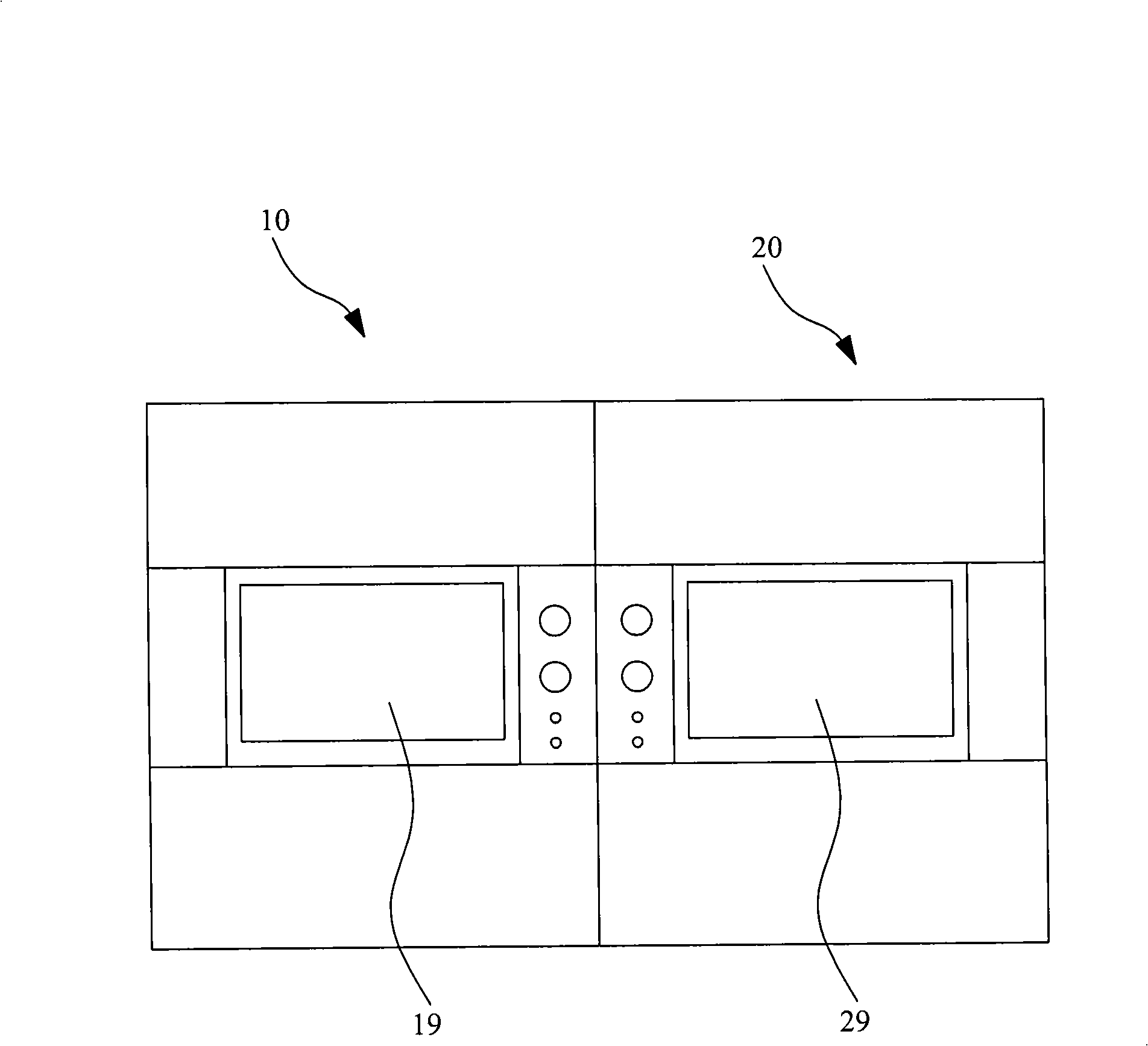
[0038] Below, refer to Figure 1 and figure 2 The foaming machine according to the present invention is described. Foaming machine according to the present invention comprises a plurality of clamping devices, only two clamping devices 10, 20 are shown in Fig. 1, but the present invention is not limited thereto, it can have more than two clamping devices . The main structure of each mold clamping device is basically the same, and the structure of the mold clamping device will be described below by taking the mold clamping device 10 as an example.

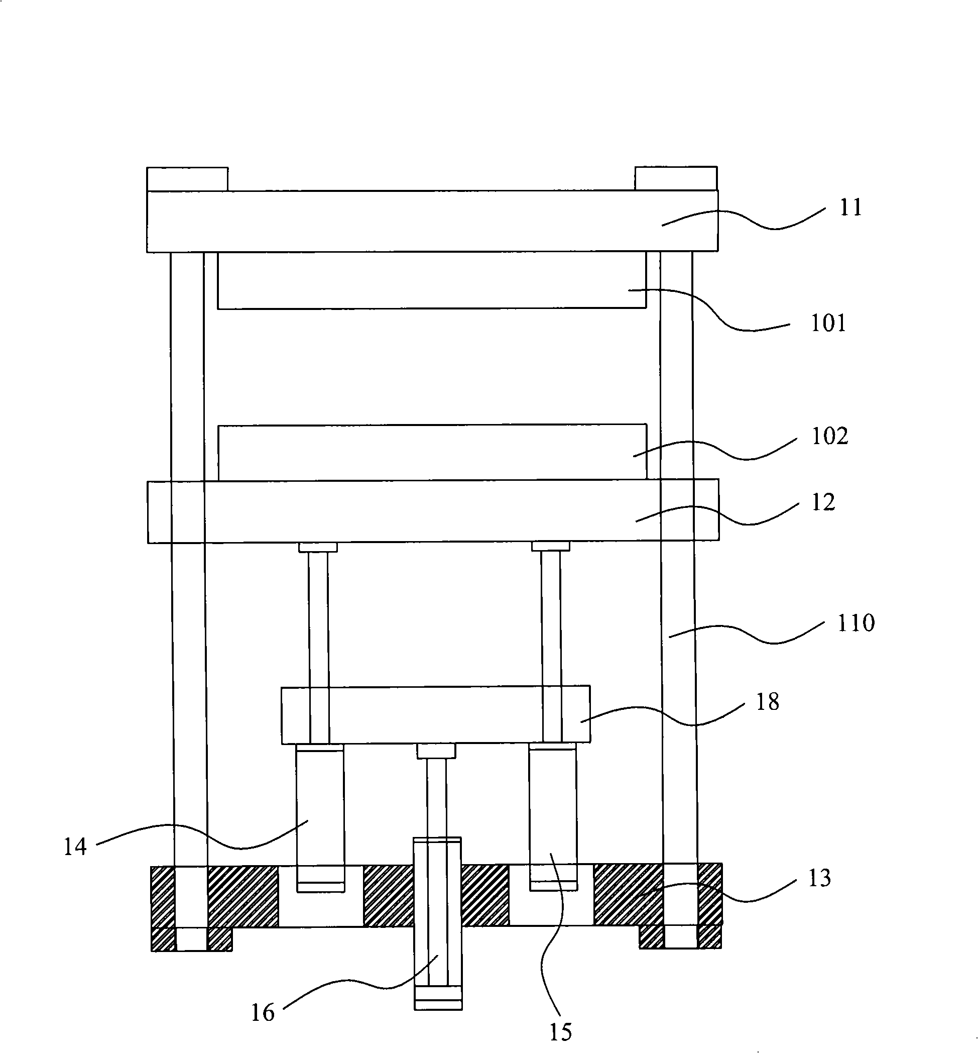
[0039] The mold clamping device 10 respectively includes a lower template 13, a middle template 12, an upper template 11, a...


PUM


Abstract

The invention provides a foaming machine which includes a clamping device. The clamping system includes a lower template which is fixed on the base of the foaming machine and is fixedly provided with a guide shaft; a middle template which is provided with a lower die, arranged above the lower template and can move up and down along the guide shaft; an upper template which is provided with an upper die opposite to the lower die and is arranged on the top part of the guide shaft and is above the middle template; an oil cylinder which is arranged between the middle template and the lower template and is characterized in that the oil cylinder is a secondary oil cylinder. The foaming machine according to the invention can reduce the height of the machine, increasing the parallelism of a compression die, improving the utilization efficiency of energies and improving the automatization of the machine.

Description

technical field [0001] The invention relates to a foaming machine and a control method thereof. Background technique [0002] Polystyrene is a thermoplastic material. After being heated (the heating method is mainly steam heating at high temperature) and foamed, each cubic decimeter contains 3 to 6 million independent airtight bubbles, and the contained air volume is more than 98%. Because the weight per unit volume of thermoplastic material is very light after foaming, it has become one of the widely used materials. [0003] At present, the foaming machine used for foaming materials such as polystyrene is usually a manual foaming machine, which uses an upper oil cylinder to drive the middle template to work. The machine height of this foaming machine is too high, which is not convenient for workers to operate. In addition, there are also some manual vertical foaming machines. Although they are driven by the lower oil cylinder, because the height of the machine is too high...

Claims


Application Information

Patent Timeline
Patent Type & Authority Applications(China)
IPC IPC(8): B29C44/00B29C44/58B29C44/60B29K25/00
Inventor 蔡祥山
Owner 蔡祥山
Learn More