Balance hinge

A hinge and balance technology, applied in the field of refrigerator door balance hinges, can solve the problems of inability to accurately find the controlled point or angle range, the opening angle is small, the door body falls and closes, etc., to achieve simple structure, slow movement speed, and operation reliable results

Active Publication Date: 2008-11-12
HAIER GRP CORP +1
View PDF5 Cites 22 Cited by
  • Summary
  • Abstract
  • Description
  • Claims
  • Application Information

AI Technical Summary

Problems solved by technology

[0004] The traditional hinge structure of the above-mentioned composition has the following disadvantages: the box door is limited by the spring force, so that the box door can only be stopped at a certain point or within a small angle range within the opening range of 35° to 90°. control, and the user often cannot accurately find the above-mentioned controlled point o

Method used


Image

  • Balance hinge
  • Balance hinge
  • Balance hinge

Examples


Embodiment 1

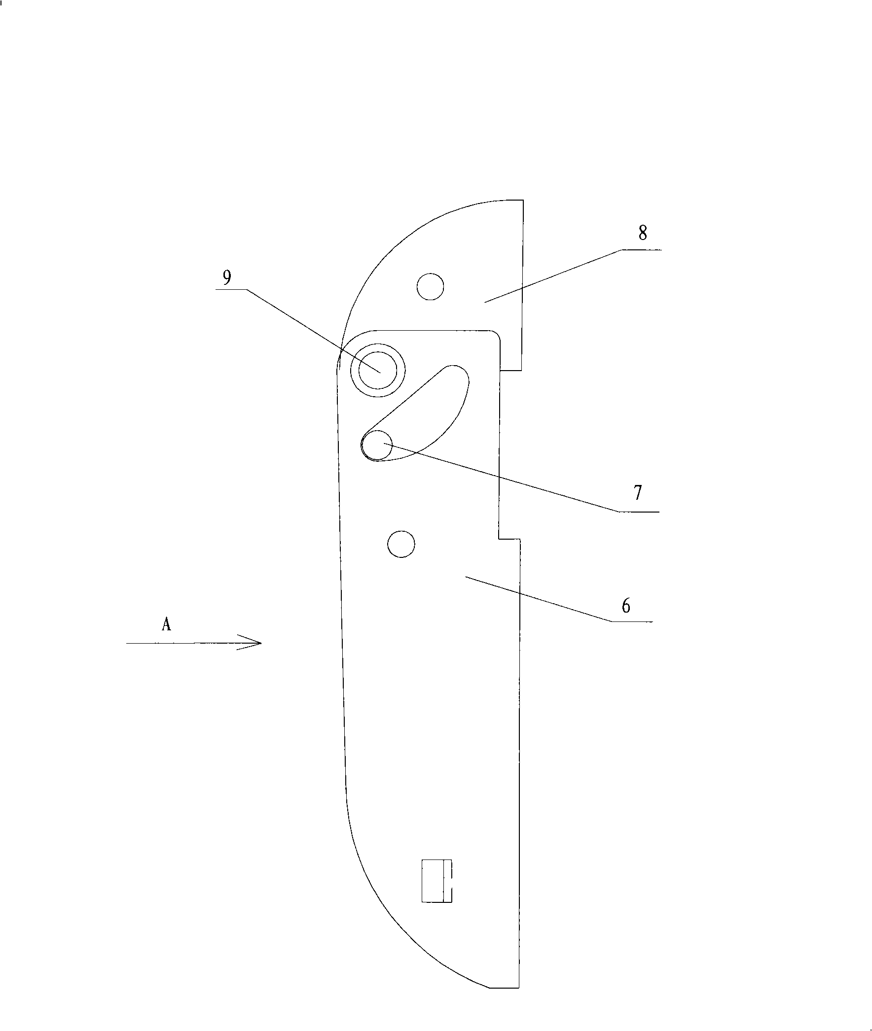
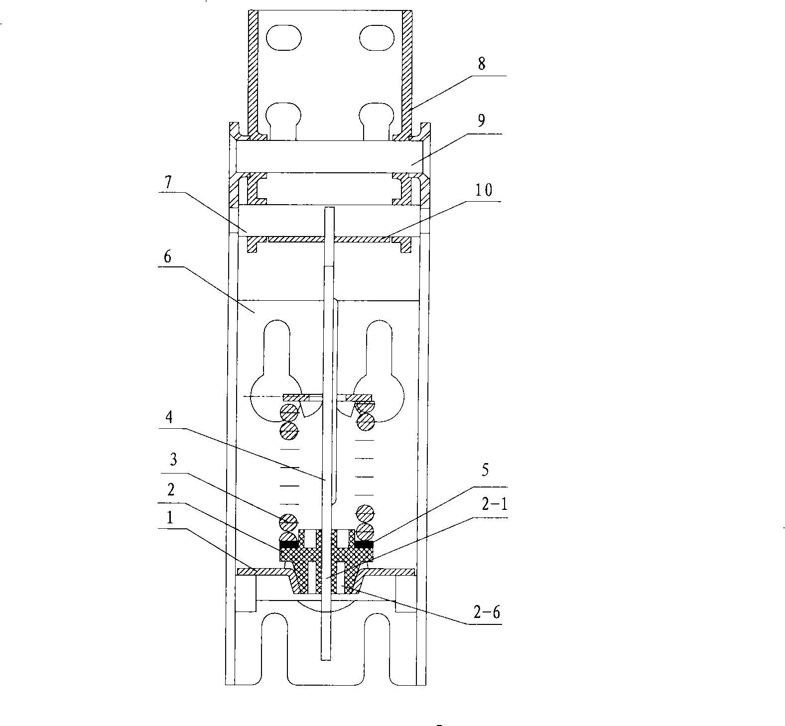
[0028] Embodiment one, such as figure 1 , 2 As shown, the balance hinge of the present invention includes a hinge shaft 9, a hinge lower shell 6 rotatable around the hinge shaft 9, a hinge upper shell 8, a guide plate 4, a spring 3, a spring lower seat 2, and a support beam fixed on the hinge lower shell 6. 1. A rocker shaft 7 is connected to the side wall of the hinge upper case 8, and the rocker shaft 7 is accommodated in the groove at the upper end of the guide plate 4, and the upper end of the guide plate 4 withstands the rocker shaft 7 by the restoring force of the spring 3. In order to avoid wear and tear, the guide plate 4 The upper end bears against the rocker shaft 7 through the bracket 10, the lower part of the guide plate 4 is inserted into the spring 3, the lower end of the guide plate 4 extends into the spring lower seat 2 and the supporting beam 1, and the spring 3 is against the stopper of the guide plate 4 and the spring lower seat 2 between. Wherein, the fi...

Embodiment 2

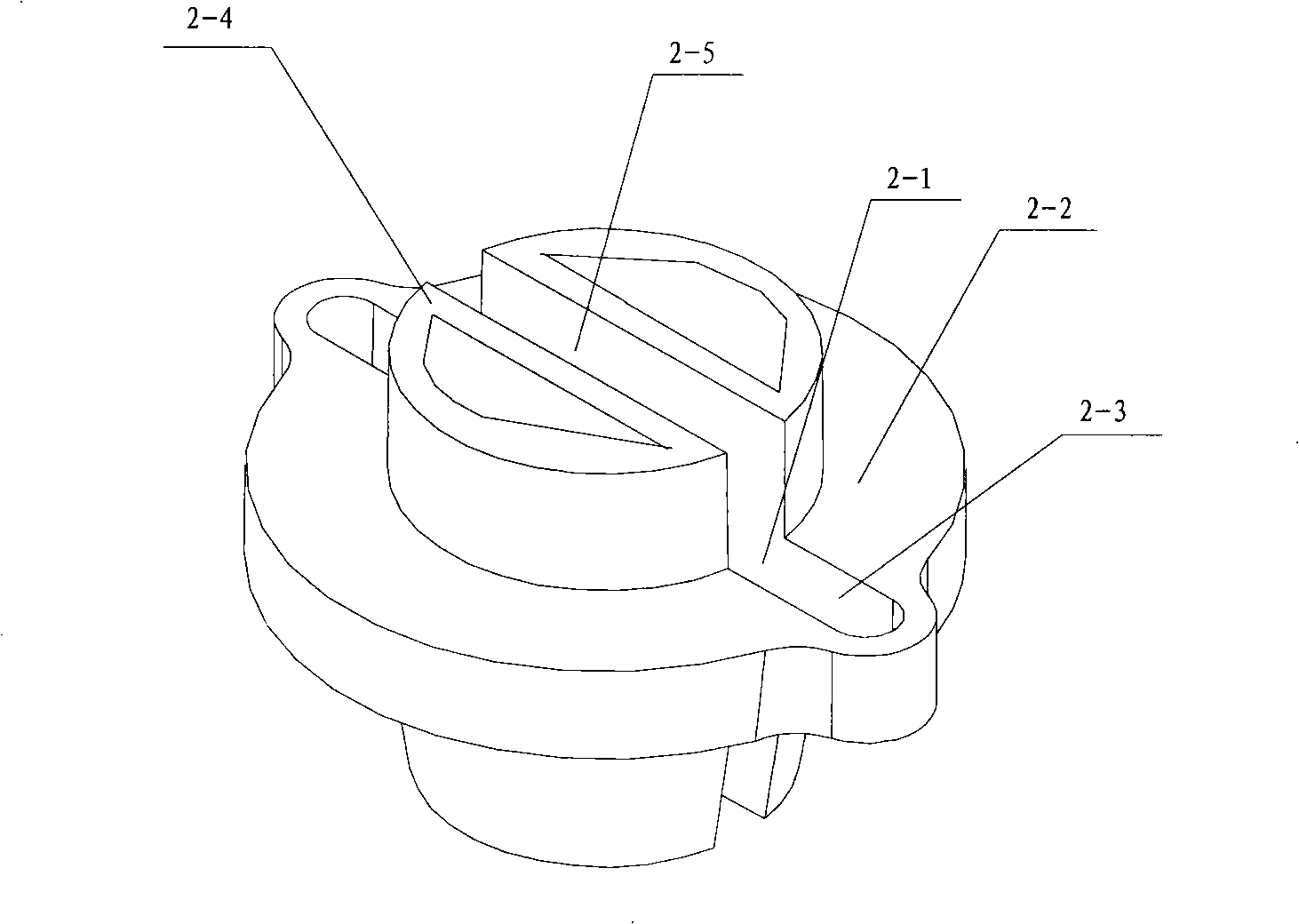
[0033] Embodiment two, refer to figure 2 , 3 , differs from Embodiment 1 in that: the top of the round platform under the spring seat 2 of this embodiment has a cylinder 2-4 consistent with the inner diameter of the spring 3, and of course it can also be other polygonal prisms, and the cylinder 2-4 has a hole along the diameter that is consistent with the inner diameter of the spring 3. The notch 2-5 communicated with the axial through groove 2-1, the lower end of the spring 3 is sleeved on the cylinder 2-4. The lower spring seat 2 of this structure can well fix the spring 3 around the guide plate 4. In order to reduce wear and tear, a washer 5 can be placed on the cylinder 2-4. In order to save labor and facilitate processing, the cylinder 2-4 also has groove on top surface.

[0034]The technical feature based on the present invention is to use the working state that the spring tends to be released when the door is opened and compressed when the door is closed, to adjust t...


PUM


Abstract

The invention discloses a balance hinge which can solve the problem that the door of a refrigerator can not be kept in the balance status when the door is opened ranging from 35 degree to 90 degree in the prior art. The technical proposal adopted by the invention is that a lower spring base is added and a supporting cross beam which is provided with a cone-shaped hole the shape of which is corresponding to a cone frustum is arranged for matching; the lower spring base is a cone frustum narrowing downwards and provided with an axial through groove through the diameter, therefore, when a guide plate moves downwards, the axial through groove tightens inwards and the friction force with the guide plate increases to cause that the door body never moves automatically due to the function of gravity and the spring force when the door is opened by certain degree range but stays in any point of the opening degree range to be controlled in balance.

Description

technical field [0001] The invention belongs to the technical field of refrigerator hinges, and in particular relates to a refrigerator door balance hinge. Background technique [0002] The traditional freezer door is set on the top of the freezer box, and the door is supported by a hinge set at the rear end of the freezer. Refer to figure 1 , 2 , the hinge is composed of a hinge upper shell 8 fixed on the outside of the box door and a hinge lower shell 6 fixed on the outside of the box body. The hinge upper shell 8 and the hinge lower shell 6 are connected by a hinge shaft 9 to form a rotatable structure. The hinge upper shell 8 A rocker shaft 7 is connected to the side wall. The rocker shaft 7 is accommodated in the groove at the upper end of the guide plate 4. The guide plate withstands the rocker shaft by the restoring force of the spring 3. The spring 3 is inserted into the lower part of the guide plate. The lower end of the spring 3 is supported by a crossbeam suppor...

Claims


Application Information

Patent Timeline
IPC IPC(8): E05D3/02E05D11/10F25D23/02
Inventor 李标张天会孟兆福徐蕾徐海光
Owner HAIER GRP CORP
Why Eureka
Try Eureka