
Engine startup pressure reduction cam axle component

An engine starting and camshaft technology, which is applied to engine components, machines/engines, mechanical equipment, etc., can solve problems such as the impact of exhaust emissions, and achieve the effect of reasonable position design and reliable starting and decompression.

Inactive Publication Date: 2008-11-12
LONCIN MOTOR
View PDF0 Cites 1 Cited by
  • Summary
  • Abstract
  • Description
  • Claims
  • Application Information

AI Technical Summary

Problems solved by technology

[0006] The purpose of the present invention is to provide a kind of engine starting decompression camshaft assembly, to solve the problem that the existing starting decompression mechanism has an influence on the exhaust emission when the engine starts

Method used

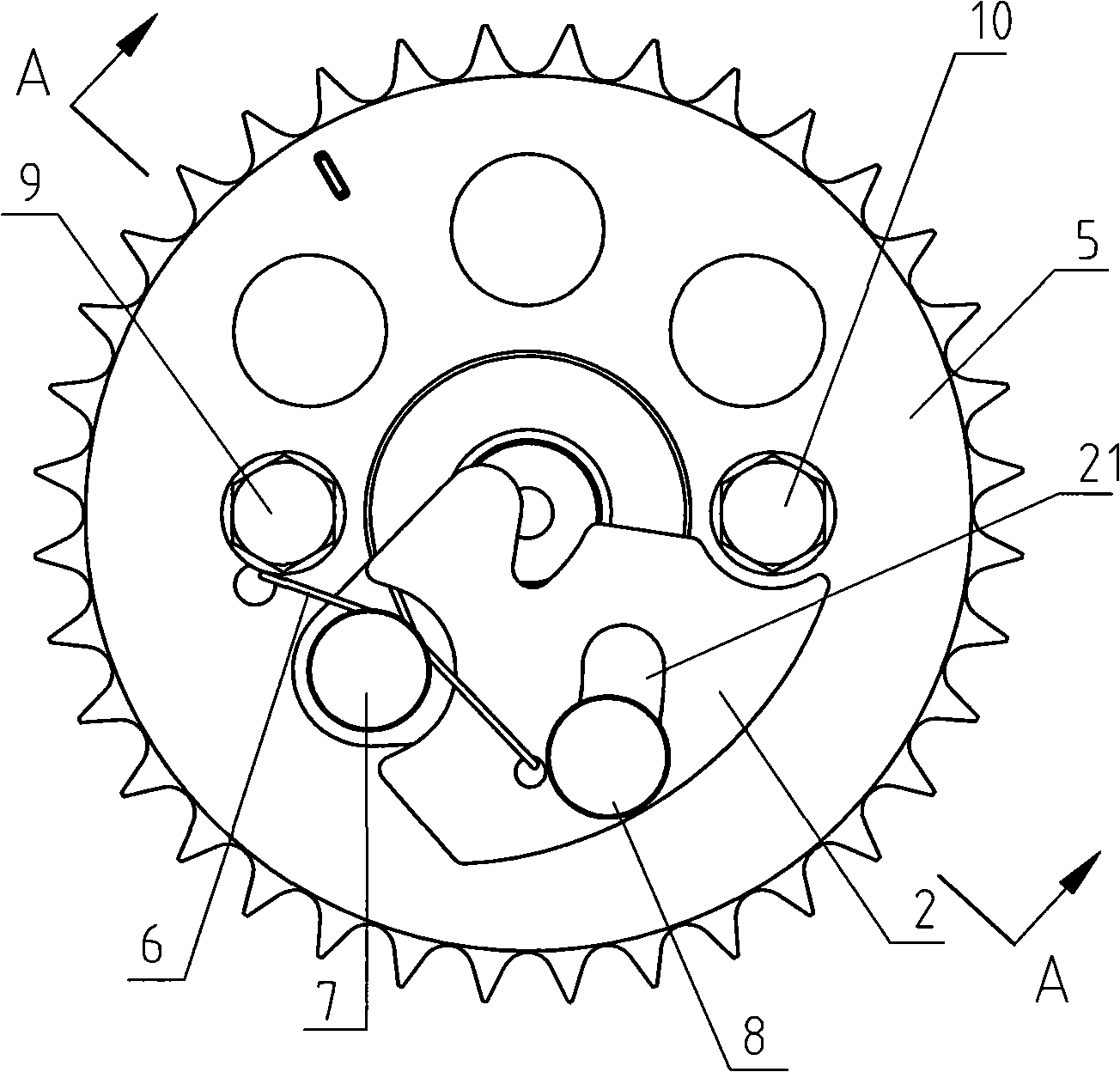
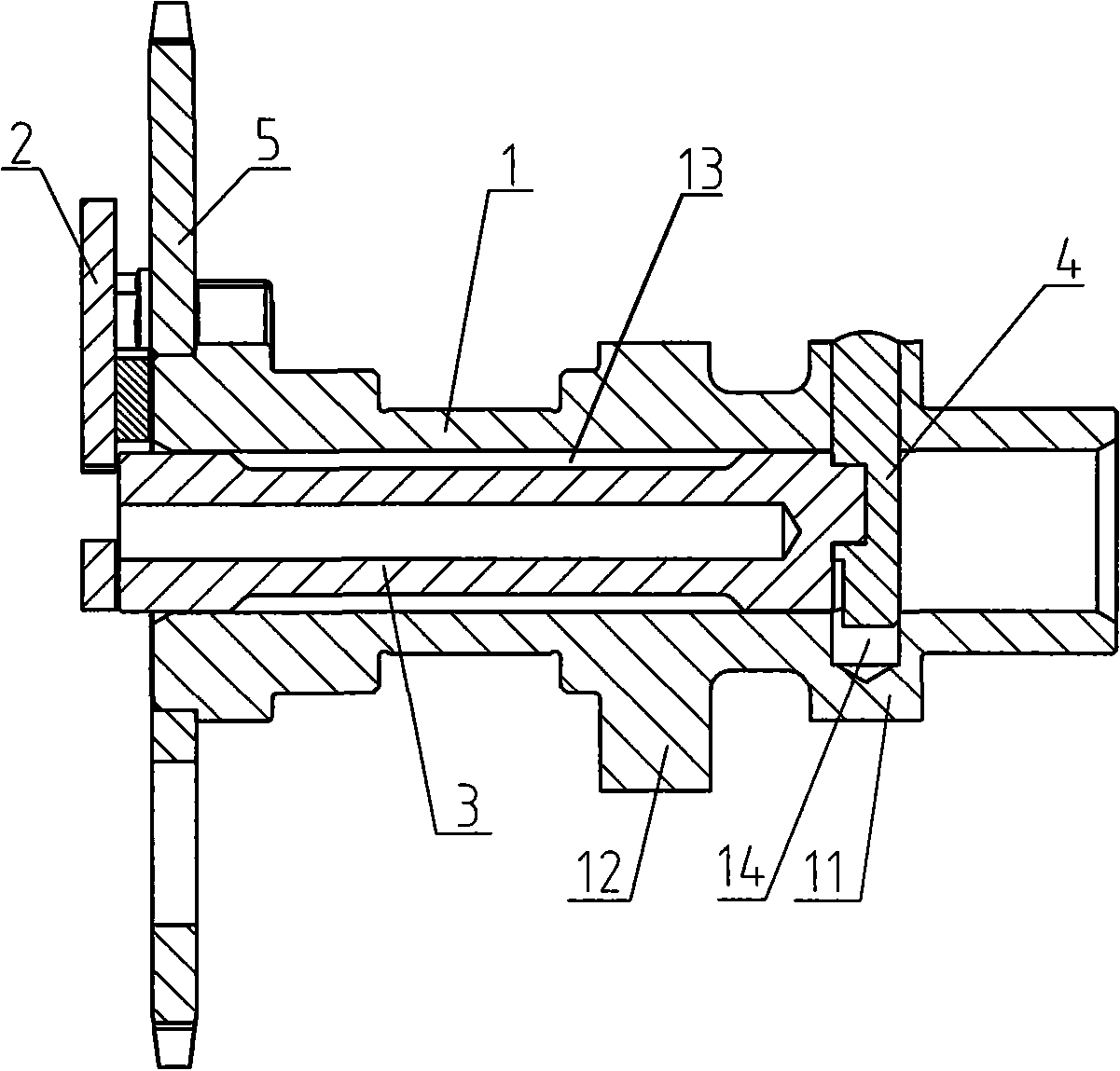
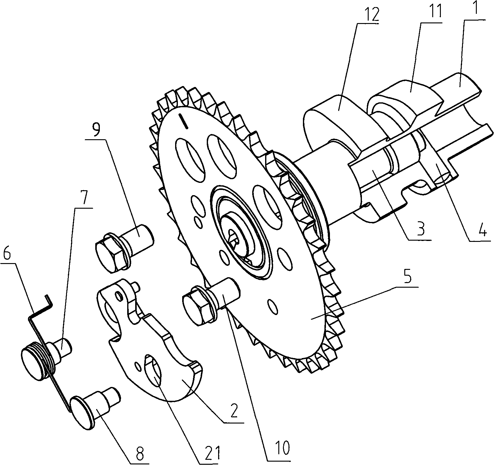

Image

  • Engine startup pressure reduction cam axle component
  • Engine startup pressure reduction cam axle component
  • Engine startup pressure reduction cam axle component

Examples


Embodiment Construction

[0016] Below in conjunction with accompanying drawing and embodiment the present invention will be further described:

[0017] Such as figure 1 , figure 2 and image 3 Shown, a kind of engine starting decompression camshaft assembly is used on the motorcycle engine, consists of camshaft 1, centrifugal flying weight 2, flying weight shaft 3, pressure reducing valve body 4, timing driven wheel 5, spring 6, Locating pin 7, limit pin 8 and bolt 9,10 are formed. There are intake cam 11 and exhaust cam 12 on the camshaft 1, the timing driven wheel 5 is fixed on the end of the camshaft 1 with bolts 9 and 10, and the centrifugal flying weight 2 is installed on the end face of the timing driven wheel 5 with the positioning pin 7 Above, the centrifugal flying weight 2 can rotate around the positioning pin 7 under the action of centrifugal force. The spring 6 is a torsion spring and is set on the positioning pin 7. One end of the spring 6 is hung in the hole on the end face of the ti...


PUM


Abstract

The invention discloses a starting decompression camshaft component of an engine, which comprises a camshaft (1), a centrifugal flyweight (2), a timing driven wheel (5) and a column-shaped decompression valve (4) which is driven by the centrifugal flyweight (2). The camshaft (1) is provided with an admission cam (11) and an exhaust cam (12), the timing driven wheel (5) is fixed at the end of the camshaft, (1) and the centrifugal flyweight (2) is installed on the end face of the timing driven wheel (5). A spring (6) is arranged between the centrifugal flyweight (2) and the timing driven wheel (5). The position of the working end of the decompression valve (4) is corresponding to the base circle surface of the admission cam (11). Driven by the centrifugal flyweight (2), the working end of the decompression valve (4) can be higher than or lower than the base circle surface of the admission cam (11). In the invention, the position design of the working end of the decompression valve on the camshaft is more reasonable, therefore, not only the starting decompression can be effectively and reliably realized, but also the exhaust of unburned gas mixture into atmosphere when the engine is started can be avoided. The starting decompression camshaft component of the invention is environment protective and energy saving.

Description

technical field [0001] The invention belongs to the technical field of engines, and in particular relates to an engine camshaft assembly equipped with a starting decompression mechanism. Background technique [0002] When the engine starts, the piston compresses the gas sucked into the cylinder. According to the normal working mechanism of the valve mechanism, the intake and exhaust valves are closed at this time. Near the end of compression, the gas pressure in the cylinder is very high. It will make it very difficult to start. For an electric start engine, the load of the start motor will reach the highest momentarily; for an engine started by hand or foot, it will feel laborious to operate. If the force applied to the control handle or foot start lever cannot be overcome When the above-mentioned gas pressure is reached, the control handle or the foot start lever will rebound, which may injure the human body or damage the machine. [0003] In order to solve the problem th...

Claims


Application Information

Patent Timeline
IPC IPC(8): F01L13/08
Inventor 欧阳先军郑小兵焦胜林王剑平张维清孟红梅
Owner LONCIN MOTOR
Learn More