
Wave power generating system

A wave power generation and wave technology, which is applied in ocean energy power generation, engine components, machines/engines, etc., can solve the problem that the wave power generation system cannot adapt to the ebb and flow of the tide, and achieves the effect of simple structure and mature technology.

Inactive Publication Date: 2010-06-09
陈施宇 +1
View PDF8 Cites 0 Cited by
  • Summary
  • Abstract
  • Description
  • Claims
  • Application Information

AI Technical Summary

Problems solved by technology

[0003] The technical problem to be solved by the present invention is to provide a wave power generation system to solve the problem that the current wave power generation system cannot adapt to the ebb and flow of tides

Method used


Image

  • Wave power generating system
  • Wave power generating system
  • Wave power generating system

Examples


specific Embodiment approach 1

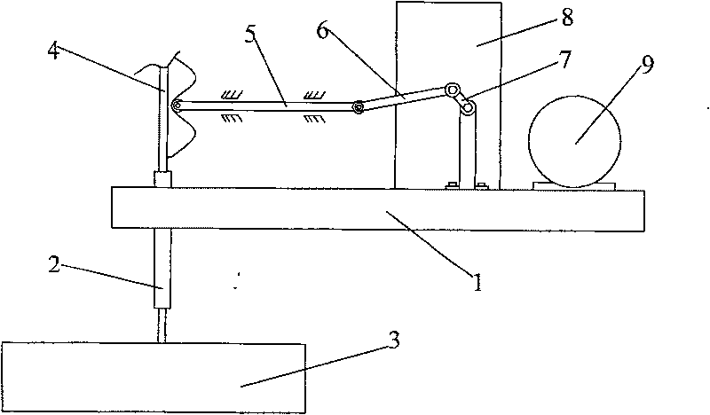
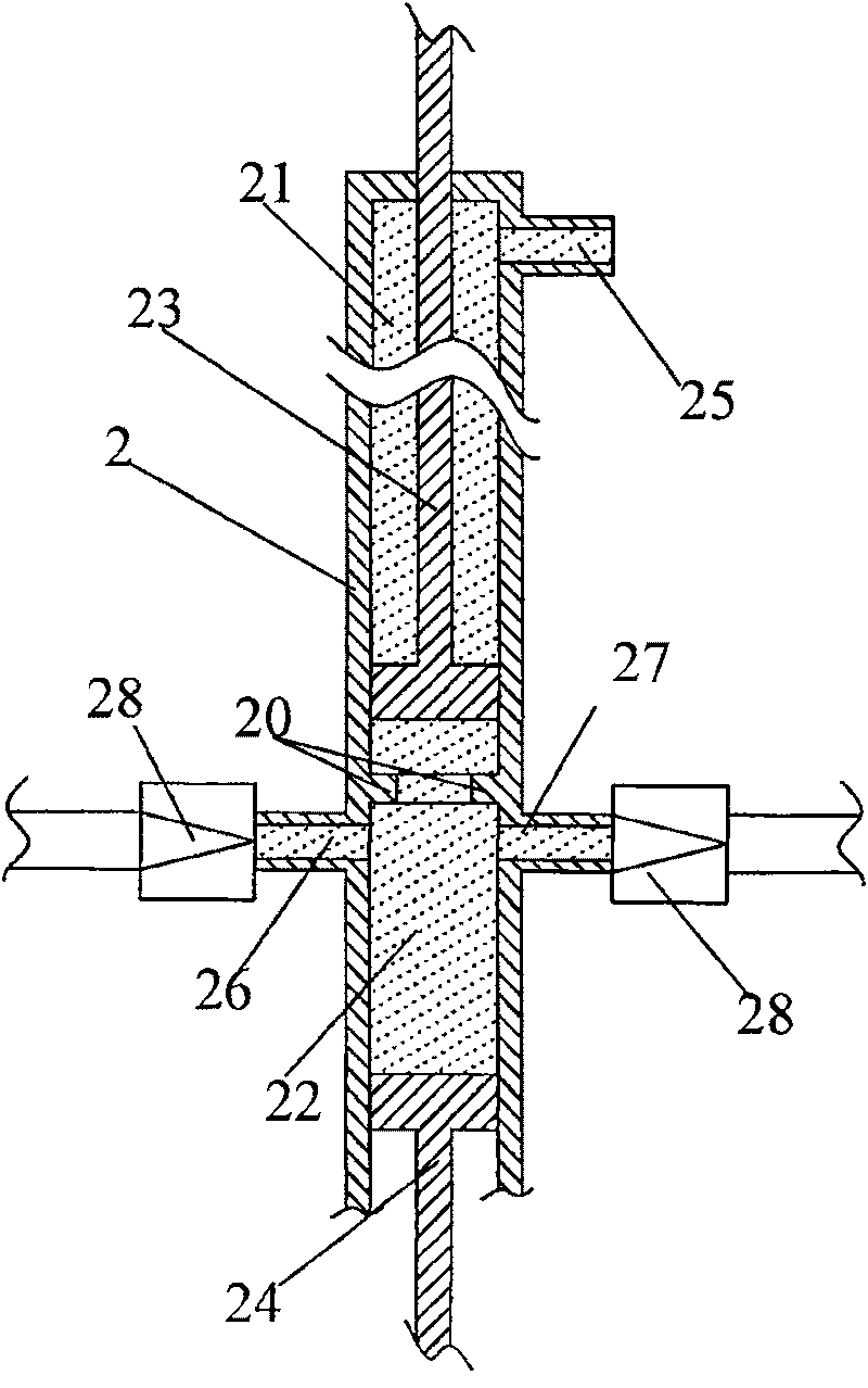
[0023] The wave power generation system provided by this specific embodiment is suitable to be built on a platform in shallow sea near the coast, and it mainly includes: a wave energy pickup unit, a wave adaptation unit, a motion conversion unit and a generator.

[0024] Such as figure 1 As shown, the entire system is set up on platform 1. The wave energy pick-up unit is used to pick up the energy of waves. The wave energy pick-up unit in this specific embodiment mainly includes a float 3, and the float 3 floats on the water surface below the platform 1. As the waves rise and fall, the energy of the waves is converted into up and down. reciprocating motion. The buoy 3 is power-connected with the motion conversion unit through the wave adaptation unit, transfers energy to the motion conversion unit, and is converted into rotational motion by the motion conversion unit to drive the generator to generate electricity.

[0025] In order to adapt to the different sizes of the wave...

specific Embodiment approach 2

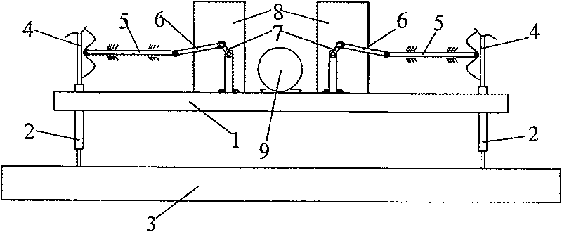
[0032] In order to make the system more optimized, the image 3 As shown, the two systems in Embodiment 1 are symmetrically arranged on one platform 1, and the two floats 3 are connected into one body, then the power is transmitted through two channels and jointly drives a generator 9 to generate electricity.

specific Embodiment approach 3

[0033] can also be like Figure 4 As shown, several groups image 3 The systems shown are juxtaposed, and the movement generated by several floats 3 drives two long crankshafts 7 after passing through their respective hydraulic telescopic rods 2 and wave mechanism 4, ejector rod 5, and rocker 6. Each crankshaft 7 A gearbox 8 is respectively connected to drive a generator 9 to generate electricity. In actual use, extend the system from the sea to the sea, and adjust the spacing between each group of units so that the spacing between every two floats 3 is about an odd multiple of half the wave pitch, and one float 3 is at the wave crest , its adjacent two floats 3 such as Figure 4 If it is exactly in the trough, the system can work together to achieve the best power generation effect.


PUM


Abstract

The invention relates to a wave electricity-generating system which comprises a wave energy colleting module, a motion and transformation module and a generator and a wave adaptation module mounted for adapting the waves with parameters, wherein, the wave energy colleting module is connected with the motion and transformation module by wave adaptation module; an output end of the motion and transformation module is dynamically connected with the generator; the wave adaptation module comprises a ripple mechanism which is dynamically connected with the energy colleting module and reciprocates atvertical direction along with the heaving of waves; one side of the ripple mechanism is provided with a wavy face, the parameters of which are matched with waves of different sizes. As wave adaptation unit is mounted and the wave adaptation unit comprises the ripple mechanism, by adopting the technical proposal of the invention, the wave electricity-generating system can adapt to the waves with different sizes by changing the size of wavy face on the ripple mechanism, so that the generating system can generate electricity normally as long as the wave height is within 0.5 to 10m.

Description

technical field [0001] The invention relates to a power generation device, in particular to a wave power generation system, in particular to a wave power generation system which utilizes ocean waves to generate power and can adapt to tides. Background technique [0002] The existing wave power generation devices can be roughly divided into two types in terms of their energy conversion methods: one is to use the driving force of the waves to convert the wave energy into high-speed flowing gas, and then the gas drives the air turbine to rotate its blades. generate electricity. For example, Japan's "Haiming" power generation ship, "Giant Whale" wave power generation system, etc. However, due to the use of airflow to drive the turbine to generate electricity, the time between the gas and the blades is short, the energy absorption is small, and the energy conversion rate is low. According to reports, only 16% of the wave energy can be converted into electrical energy theoretical...

Claims


Application Information

Patent Timeline
Patent Type & Authority Patents(China)
IPC IPC(8): F03B13/14F03B13/26
CPCY02E10/38Y02E10/30
Inventor 陈施宇林其访
Owner 陈施宇
Learn More