Wind power rotor shaft structure

A rotor shaft and wind power technology, applied in the field of wind rotor shaft structure, can solve the problems of inability to reduce noise, no operation and installation, and inconvenient operation and use by users

Pending Publication Date: 2021-05-14
西安利和愽机械制造有限公司
View PDF7 Cites 0 Cited by
  • Summary
  • Abstract
  • Description
  • Claims
  • Application Information

AI Technical Summary

Problems solved by technology

[0004] The purpose of the present invention is to provide a wind rotor shaft structure to solve the problem that the drive system of the existing wind power generator proposed in the above background technology does not have the function of facilitating the operation

Method used


Image

  • Wind power rotor shaft structure
  • Wind power rotor shaft structure
  • Wind power rotor shaft structure

Examples


Embodiment Construction

[0026] The following will clearly and completely describe the technical solutions in the embodiments of the present invention with reference to the accompanying drawings in the embodiments of the present invention. Obviously, the described embodiments are only some, not all, embodiments of the present invention. Based on the embodiments of the present invention, all other embodiments obtained by persons of ordinary skill in the art without making creative efforts belong to the protection scope of the present invention.

[0027] In the description of the present invention, unless otherwise stated, the meaning of "plurality" is two or more; the terms "upper", "lower", "left", "right", "inner", "outer" , "front end", "rear end", "head", "tail", etc. indicate the orientation or positional relationship based on the orientation or positional relationship shown in the drawings, and are only for the convenience of describing the present invention and simplifying the description, rather...


PUM


Abstract

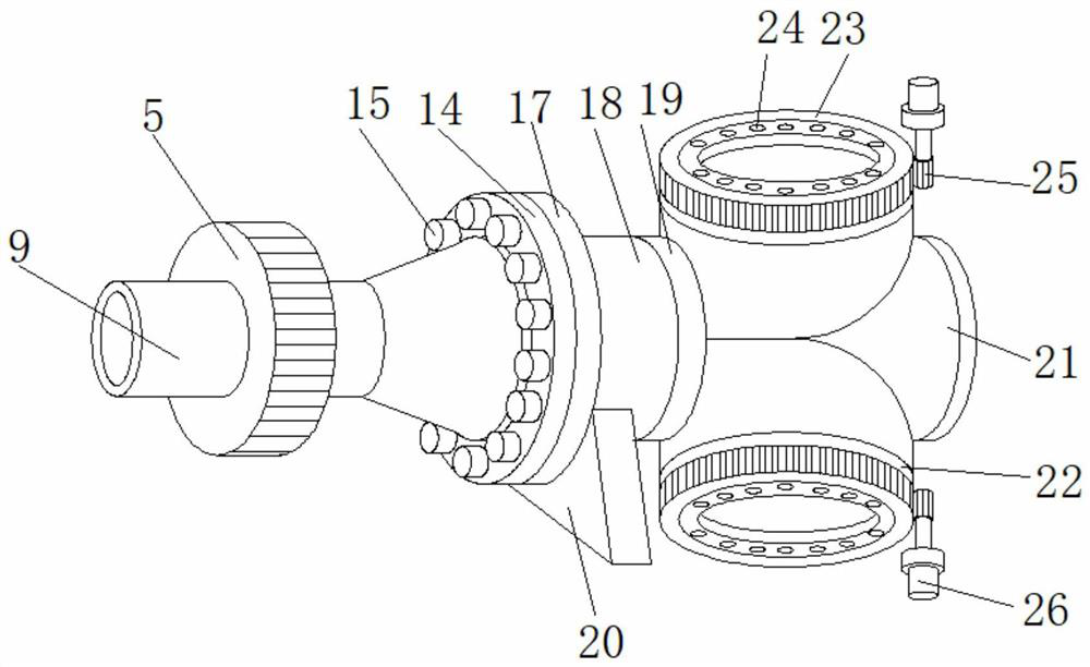
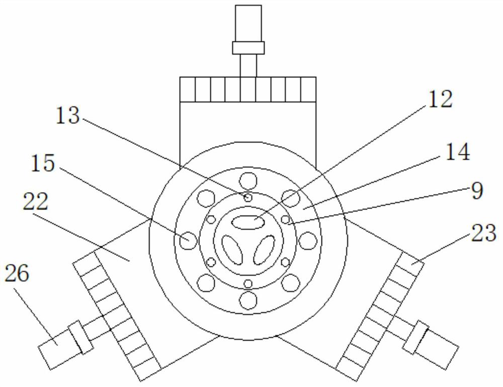
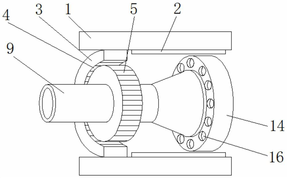
The invention relates to a wind power rotor shaft structure. The structure comprises a shell and an electronic winding, wherein a sound absorption sponge is arranged below the shell, a middle stator is arranged at one side of the sound absorption sponge, the electronic winding is arranged at one side of the middle stator, a generator rotor is arranged below the electronic winding, mounting discs are arranged at the two sides of the generator rotor, permanent magnets are mounted on the surfaces of the mounting discs, a front rotating disc is arranged at one side of each permanent magnet, a spindle is mounted in the middle of the front rotating disc, and a rear rotating disc is arranged at the other side of the spindle. The wind power rotor shaft structure has the beneficial effects that the stability of normal rotation of the spindle can be better ensured through the front rotating disc and the rear rotating disc which are mounted above the spindle, so that the working effect of a whole device is better; and the front rotating disc and the rear rotating disc form a rotating structure through the spindle, so that the whole device can better generate electricity normally through mutual cooperation of the rear rotating disc and the front rotating disc.

Description

technical field [0001] The invention relates to the technical field of wind rotor shaft structures, in particular to a wind rotor shaft structure. Background technique [0002] With the steady increase of modern electricity consumption, new energy sources gradually replace thermal power generation, and solar power generation, hydropower generation, and wind power generation appear. As an increasingly mature non-polluting power generation technology, wind power generation is used in reality. It is becoming more and more widespread. The principle of wind power generation is to use the wind to drive the rotor blades of the wind turbine to rotate, and then increase the speed of rotation through the speed increaser to promote the generator to generate electricity. According to the current wind power generation technology, it is about Three meters of breeze speed (the degree of breeze) can start to generate electricity. The rotor is a key part of the wind generator, and its struct...

Claims


Application Information

Patent Timeline
IPC IPC(8): F03D1/06F03D9/25F03D13/10F03D80/00
CPCF03D1/065F03D1/0658F03D9/25F03D13/10F03D80/00F05B2260/96Y02E10/72
Inventor 江俊
Owner 西安利和愽机械制造有限公司
Why Eureka
Try Eureka