Probe unit and detection apparatus

A technology of probe unit and inspection device, applied in the direction of measuring device, thin plate connection, manufacturing measuring instrument, etc., can solve the problems of not easy, twisted and damaged blade-type probes, etc.

Active Publication Date: 2008-11-12
NIHON MICRONICS
View PDF1 Cites 8 Cited by
  • Summary
  • Abstract
  • Description
  • Claims
  • Application Information

AI Technical Summary

Problems solved by technology

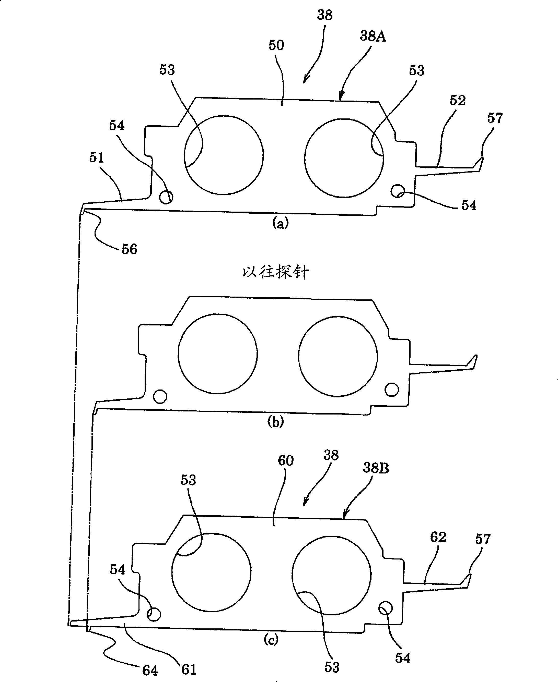
[0008] However, in the probe unit in which the above-mentioned blade-type probes with different contact positions are arranged to form a zigzag probe, it is not easy to accurately arrange a

Method used


Image

  • Probe unit and detection apparatus
  • Probe unit and detection apparatus
  • Probe unit and detection apparatus

Examples


Embodiment Construction

[0025] Hereinafter, a probe unit and an inspection device according to an embodiment of the present invention will be described with reference to the drawings. The inspection device of this embodiment is used to inspect the object to be inspected, and has a set part for carrying the object to be inspected from the outside and carrying the object to be inspected outside after the inspection is completed, and a set for supporting the object to be inspected from the setting part. Assay department that examines bodies and performs tests on them. The probe unit of the present embodiment is used for the probe unit of the measurement unit of the inspection device. In addition, since the inspection apparatus of this embodiment is substantially the same as the above-mentioned conventional inspection apparatus, the probe unit is mainly demonstrated here. In addition, the inspection device of the present invention can be applied to all devices that can use the probe unit of this embodim...


PUM


Abstract

The invention provides a probe unit and a detecting device precisely supporting the contacts to make the contacts reliably contact to the electrodes of the liquor crystal panel. The probe unit has the blade-supporting probe which makes the blades electrically contact to the probe composition with the detected body. The blade-type probe has a main body board portion, a front end side arm portion and the FPC side arm, which is composed of a first array blade-type probe and the other array blade-type probe. The first array blade-type probe provides the front end side arm portion and the aligning at the first array electrode of the intertwined distribution in the detected body, which is at the position of the front end of the front end side arm side; after the other array blade-type probe provides the front end side arm portion and the aligning at the second array electrode of the intertwined distribution in the detected body, the front end of the contact is provided with a maintaining portion to make the front arm portion of the first array blade-type probe have an approximately same length.

Description

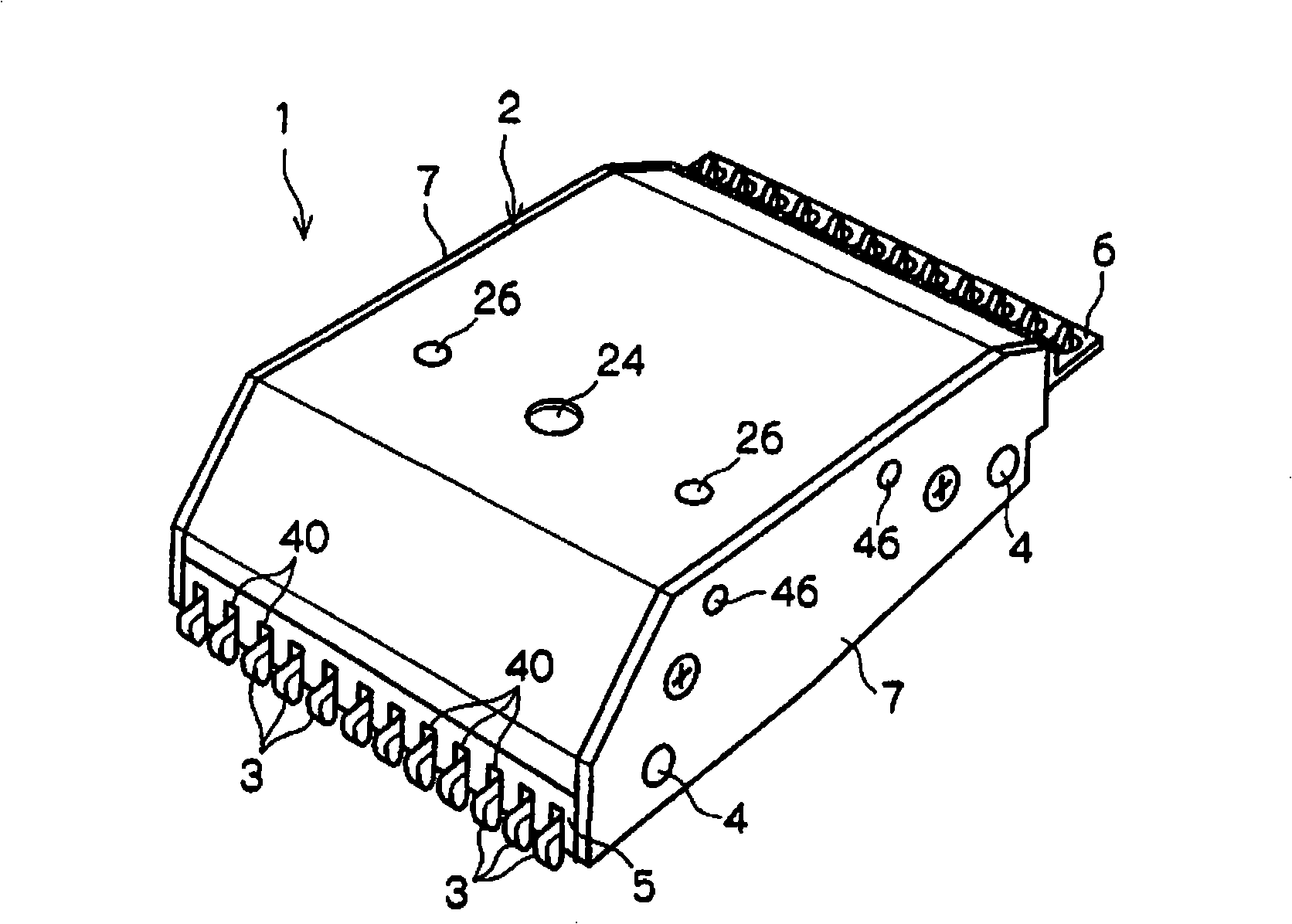
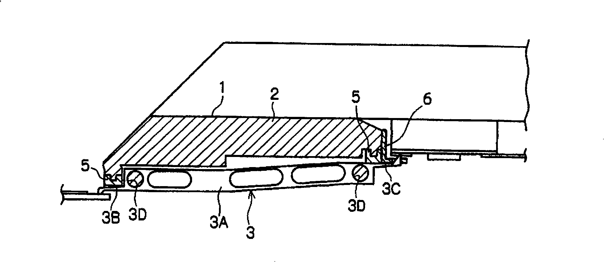
technical field [0001] The present invention relates to a probe unit and an inspection device for inspecting flat-plate objects to be inspected, such as liquid crystal panels and integrated circuits. Background technique [0002] Flat-shaped objects to be inspected such as liquid crystal panels are usually inspected using a probe unit. As such a probe unit, there is a type configured by arranging a plurality of thin-plate-shaped blade-type probes, and Patent Document 1 describes such an example. The invention of this Patent Document 1 will be schematically described below. [0003] Such as figure 2 and image 3 As shown, the probe assembly 1 includes: a block body 2, a plurality of strip-shaped probes 3 arranged side by side on the lower side of the block body 2, and a pair of elongated guide rods 4 passing through the probes 3 , a pair of grooved rods 5 for accommodating part of the probe 3 , a long guide member 6 for stabilizing the position of the needle tip on the re...

Claims


Application Information

Patent Timeline
IPC IPC(8): G01R1/073G01R31/28
CPCF16B5/02G01R1/073G01R3/00G01R31/2601G09G3/006
Inventor 久我智昭
Owner NIHON MICRONICS
Why Eureka
Try Eureka