Supercharge Your Innovation With Domain-Expert AI Agents!

Apparatus and method for separating synchronizing signal in video signal

A technology of video signal and synchronous signal, which is applied to parts of color TV, parts of TV system, TV, etc. It can solve problems such as instability of clamping loop circuit

Inactive Publication Date: 2008-11-12
HIMAX TECH LTD
View PDF0 Cites 10 Cited by
  • Summary
  • Abstract
  • Description
  • Claims
  • Application Information

AI Technical Summary

Problems solved by technology

[0005] In view of this, the object of the present invention is to provide a device and method for separating synchronous signals from video signals, so as to solve the problem of unstable clamping loop circuits in the past, and to effectively process video signals in different frequency ranges

Method used


Image

  • Apparatus and method for separating synchronizing signal in video signal
  • Apparatus and method for separating synchronizing signal in video signal
  • Apparatus and method for separating synchronizing signal in video signal

Examples


Embodiment Construction

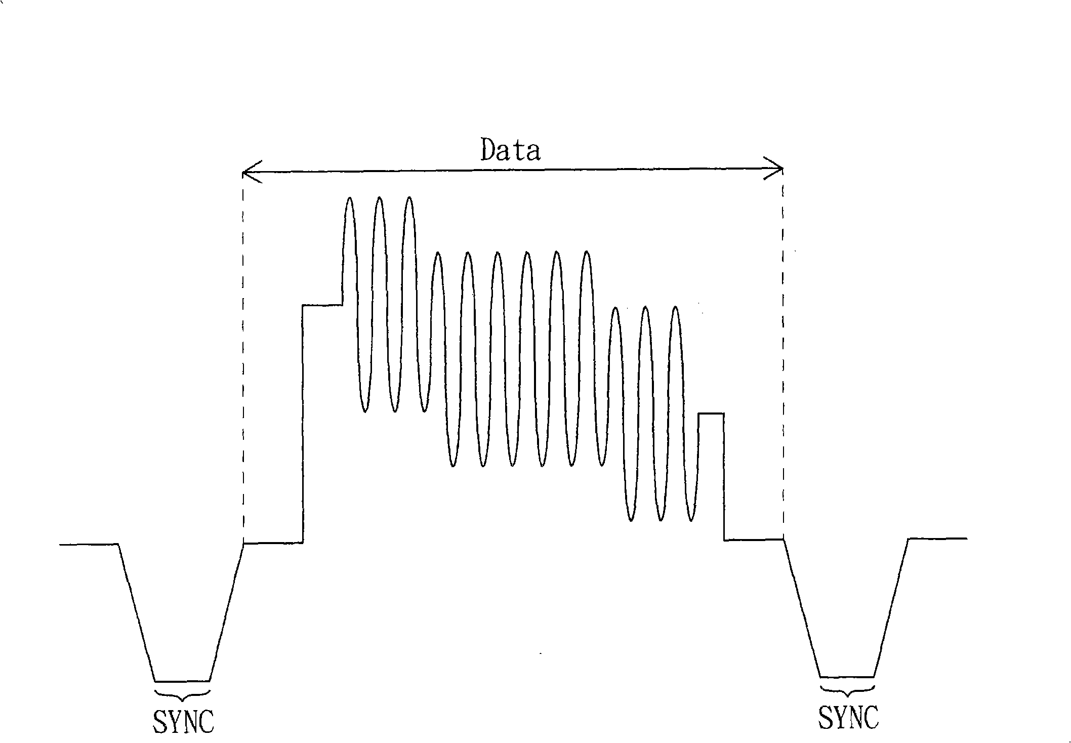
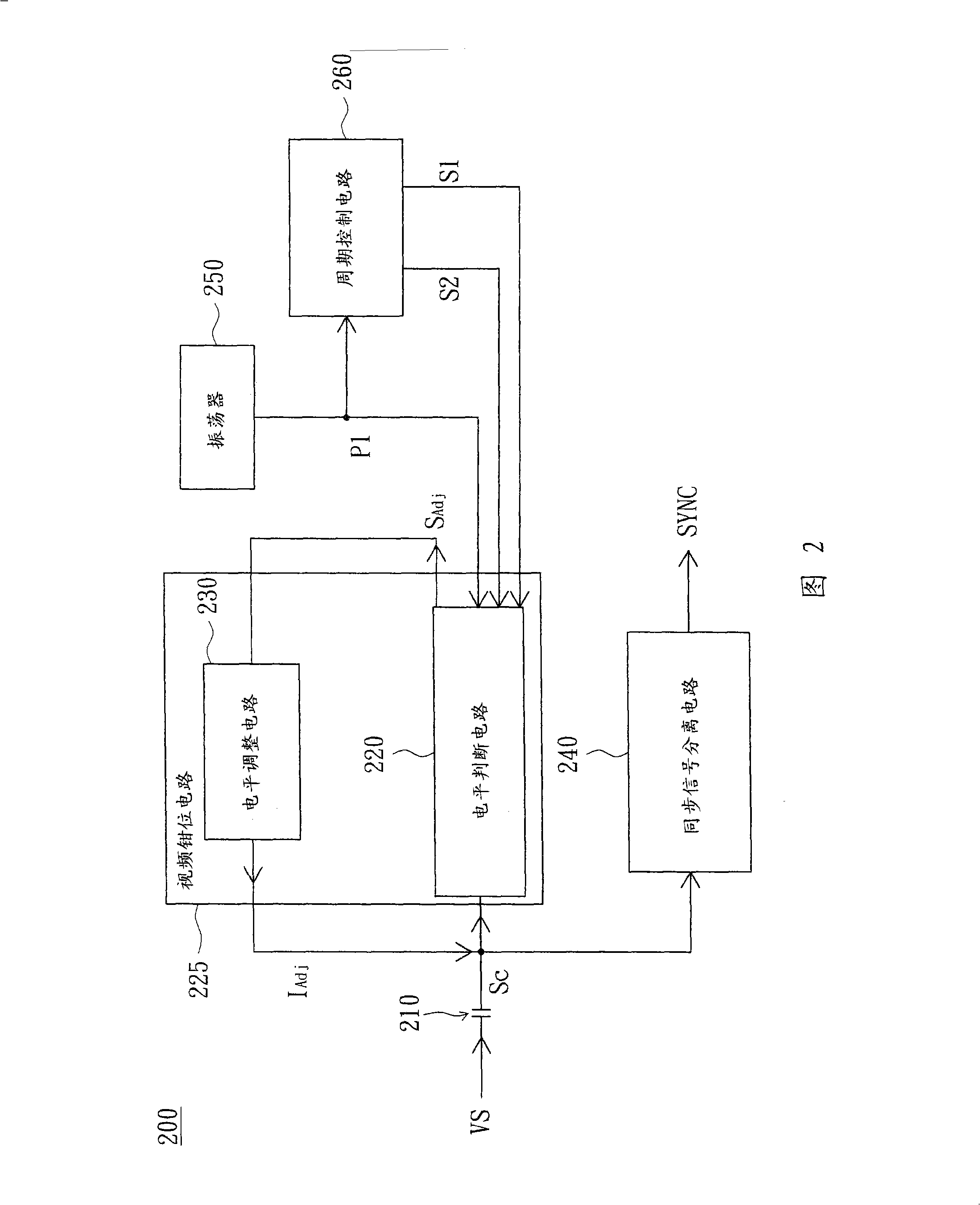
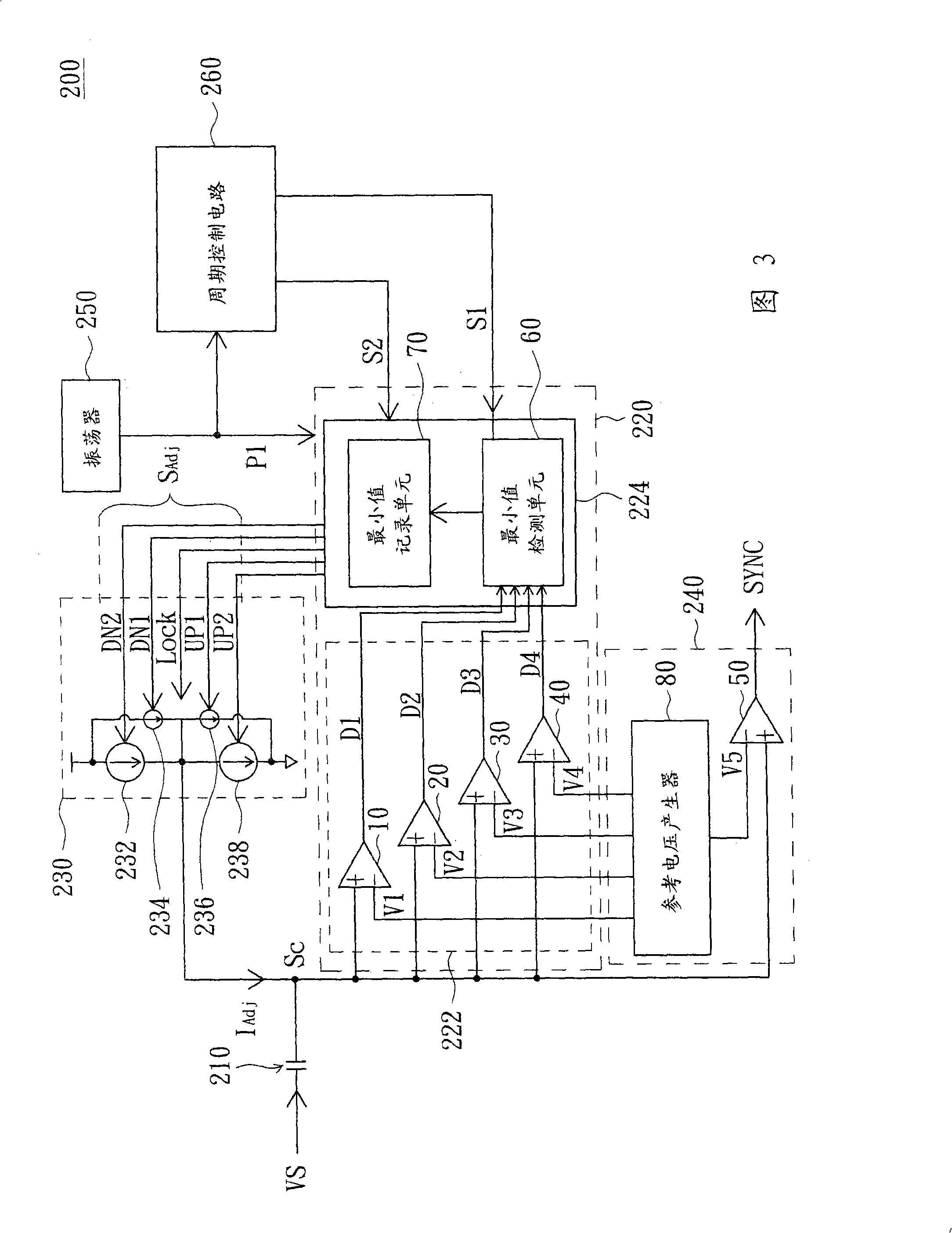
[0037] Please refer to FIG. 2 , which shows a block diagram of an apparatus for separating sync signals from video signals according to a preferred embodiment of the present invention. The device 200 for separating the synchronous signal from the video signal is disposed on a display device, such as a liquid crystal screen, for receiving the video signal VS. Wherein, the video signal VS includes a synchronous signal SYNC and a data signal Data, such as figure 1 shown. The device 200 includes a capacitor 210 , a video clamp circuit 225 and a sync signal separation circuit 240 . The video clamping circuit 225 includes a level determination circuit 220 and a level adjustment circuit 230 . The capacitor 210 is used to receive the video signal VS, and perform capacitive coupling (AC Coupling) on ​​the video signal VS to obtain the coupling signal S C .

[0038] The level judging circuit 220 is used to receive the coupling signal S C , and will couple the signal S C The voltag...


PUM


Abstract

The invention relates to a device for separating a synchronous signal from video signals and is used for receiving the video signals to obtain a coupling signal. A level judging circuit receives the coupling signal and compares the voltage of the coupling signal and a plurality of reference voltages. The reference voltages define a plurality of reference voltage intervals, one of which is a preset reference voltage interval. The level judging circuit outputs an adjusting signal according to a reference voltage interval corresponding to the smallest voltage of the coupling signal in a preset time interval. A level adjusting circuit is provided with a plurality of current sources and is used for receiving an adjust signal and adjusting the direct current level of the coupling signal by controlling the current sources. A synchronous signal separating circuit separates the synchronous signal from the coupling signal when the smallest voltage of the coupling signal substantially locates in the preset reference voltage interval.

Description

technical field [0001] The invention relates to a device and method for separating synchronous signals in signals, and in particular to a device and method for separating synchronous signals in video signals. Background technique [0002] Please refer to figure 1 , which is a waveform diagram of the video signal. The video signal includes a synchronous signal SYNC and a data signal Data. The level intervals of the data signal Data and the synchronous signal SYNC are different, and generally the possible voltage value of the data signal Data is greater than the voltage value of the synchronous signal SYNC. For the receiver of the video signal, the synchronization signal SYNC in the video signal must be separated first, and the receiver can further generate a pixel clock (Pixel Clock) according to the frequency of the synchronization signal SYNC, and process the video signal. [0003] When transmitting video signals, the output of the transmitter and the DC level that the r...

Claims


Application Information

Patent Timeline
Patent Type & Authority Applications(China)
IPC IPC(8): H04N5/08
Inventor 苏聪宜黄国展
Owner HIMAX TECH LTD
Features
  • R&D
  • Intellectual Property
  • Life Sciences
  • Materials
  • Tech Scout
  • Unparalleled Data Quality
  • Higher Quality Content
  • 60% Fewer Hallucinations
Learn More