Double seat valve

A double-seat valve and valve seat technology, which is applied in the direction of lifting valves, valve devices, mechanical equipment, etc.

Active Publication Date: 2008-11-12
TUCHENHAGEN GMBH
View PDF2 Cites 16 Cited by
  • Summary
  • Abstract
  • Description
  • Claims
  • Application Information

AI Technical Summary

Problems solved by technology

[0010]Therefore, in any case, a direct impingement by the seat clean

Method used


Image

  • Double seat valve
  • Double seat valve
  • Double seat valve

Examples


Embodiment Construction

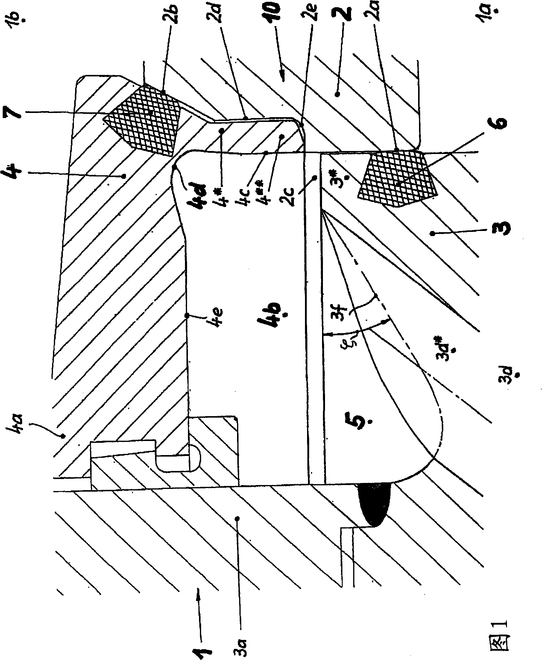
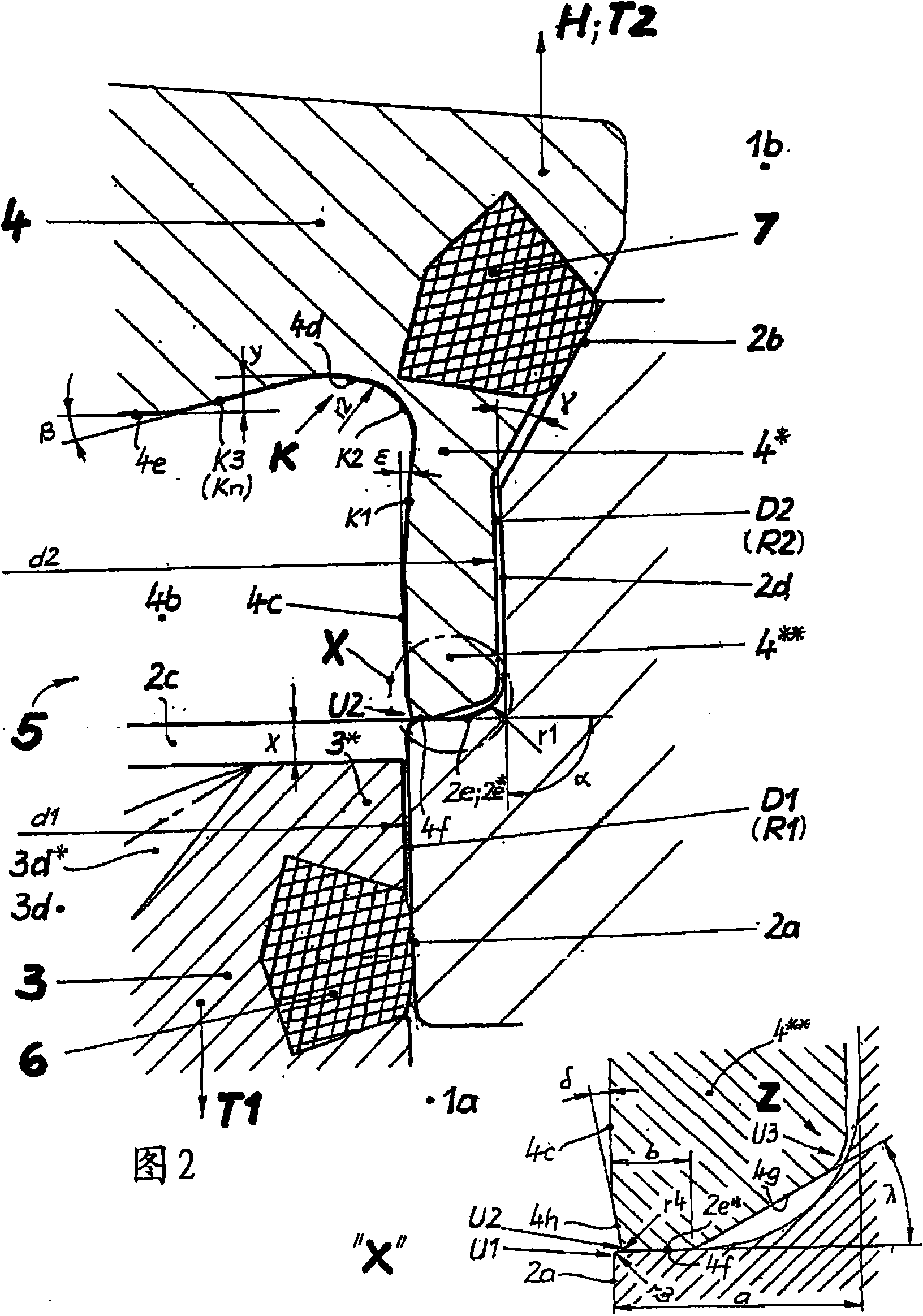
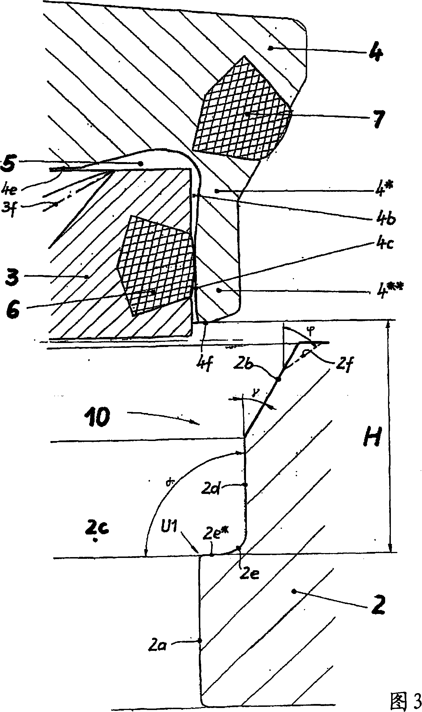
[0048] The double-seat valve 1 according to the invention (FIG. 1) basically comprises a valve chamber 10 with a first and a second valve chamber part 1a or 1b, two independently movable relative to each other with respectively assigned travel rods 3a or 4a The closing parts 3 and 4 and a valve seat ring 2, the valve seat ring establishes communication between the valve chamber parts 1a, 1b through a communication opening 2c on the inside.

[0049] In the closed position of the double-seat valve 1, the first closing part 3 (active closing part), which is designed as a sliding piston, is accommodated sealingly in a first seat surface 2a formed by the communication opening 2c, which is configured as Cylindrical seating surface. For this purpose, a first sealing ring 6 is arranged in the sliding piston 3 , which interacts with the first valve seat surface 2 a only by means of a radial offset (radial sealing ring in sliding engagement). In the closed position of the double-seat v...


PUM


Abstract

The invention relates to a double seat valve, which is capable of cleaning the seat and which is improved compared to that of the prior art, whereby a delivery as free from turbulence as possible of the seat cleaning flow into and out of the leakage cavity is ensured, and a pressure-increasing direct action upon the seat areas is reliably prevented.; This is achieved in that: the second closing element (4), when in its closed position, rests with a stopping surface (4f), which is placed on a face of its cylindrical projection (4*) and which, together with the peripheral wall (4c, 4h), forms a second wraparound edge (U2), upon the interface (2e, 2e*), and to be precise, directly upon the first seating (2a) in an adjoining manner; the peripheral wall (4c), at its end facing away from the first closing element (3), merges into a rotationally symmetric reversing surface (4d) (starting point of contour K)), and this reversing surface (4d) leads in a face (4e) of the recess (4b) oriented, in essence, perpendicular to the longitudinal axis of the second closing element (4) (leading point of contour K)), and; ; when viewing the meridian section, the reversing surface (4b) has a contour (K) with a bend-free curve, a direction vector in the leading point of the reversing surface (4d) points into a discharge borehole (3d, 3d*) centrally provided in the first closing element (3) without colliding with the first closing element (3) in the vicinity of its areas bordering the leakage cavity (5) and forming dynamic pressure.

Description

technical field [0001] The invention relates to a double-seat valve comprising two closing parts arranged in series and movable relative to each other, which, in the closed position of the double-seat valve, prevent the overflow of fluid from one valve chamber part to the other valve chamber part. flow, and defines a leakage chamber between them in the open and closed position, which communicates with the outside of the double seat valve, wherein in the closed position, the first closing part designed as a sliding piston is sealingly accommodated in an interconnected In the communication opening of the valve chamber part, and during the opening movement, it bears sealingly on the second closing part assigned to the second valve seat surface, and in the further opening movement, the second closing part is also transferred to a Open position, wherein the first closing part has a first sealing ring on its end section, which seals radially against a cylindrical first valve seat su...

Claims


Application Information

Patent Timeline
IPC IPC(8): F16K1/44
Inventor J·布尔梅斯特M·聚德尔
Owner TUCHENHAGEN GMBH
Why Eureka
Try Eureka