Gearing drive unit comprising an electronics interface

一种驱动单元、电子接口的技术,应用在电气元件、电动组件、与控制/驱动电路相连等方向,能够解决电子插头有限的变化、插入模块结构体积限制等问题,达到降低工具成本的效果

Inactive Publication Date: 2006-05-17
ROBERT BOSCH GMBH
View PDF1 Cites 20 Cited by
  • Summary
  • Abstract
  • Description
  • Claims
  • Application Information

AI Technical Summary

Problems solved by technology

[0004] The disadvantage of this arrangement is that the electrical interface of the reducer housing is only compatible with guides and seals that are completely defined in shape on the end faces of the plug-in modules
In this way, the structural volume of the plug-in module is very limited by the design of the electronic interface, and the alignment of the electronic plugs can only be varied to a limited extent

Method used


Image

  • Gearing drive unit comprising an electronics interface
  • Gearing drive unit comprising an electronics interface
  • Gearing drive unit comprising an electronics interface

Examples


Embodiment Construction

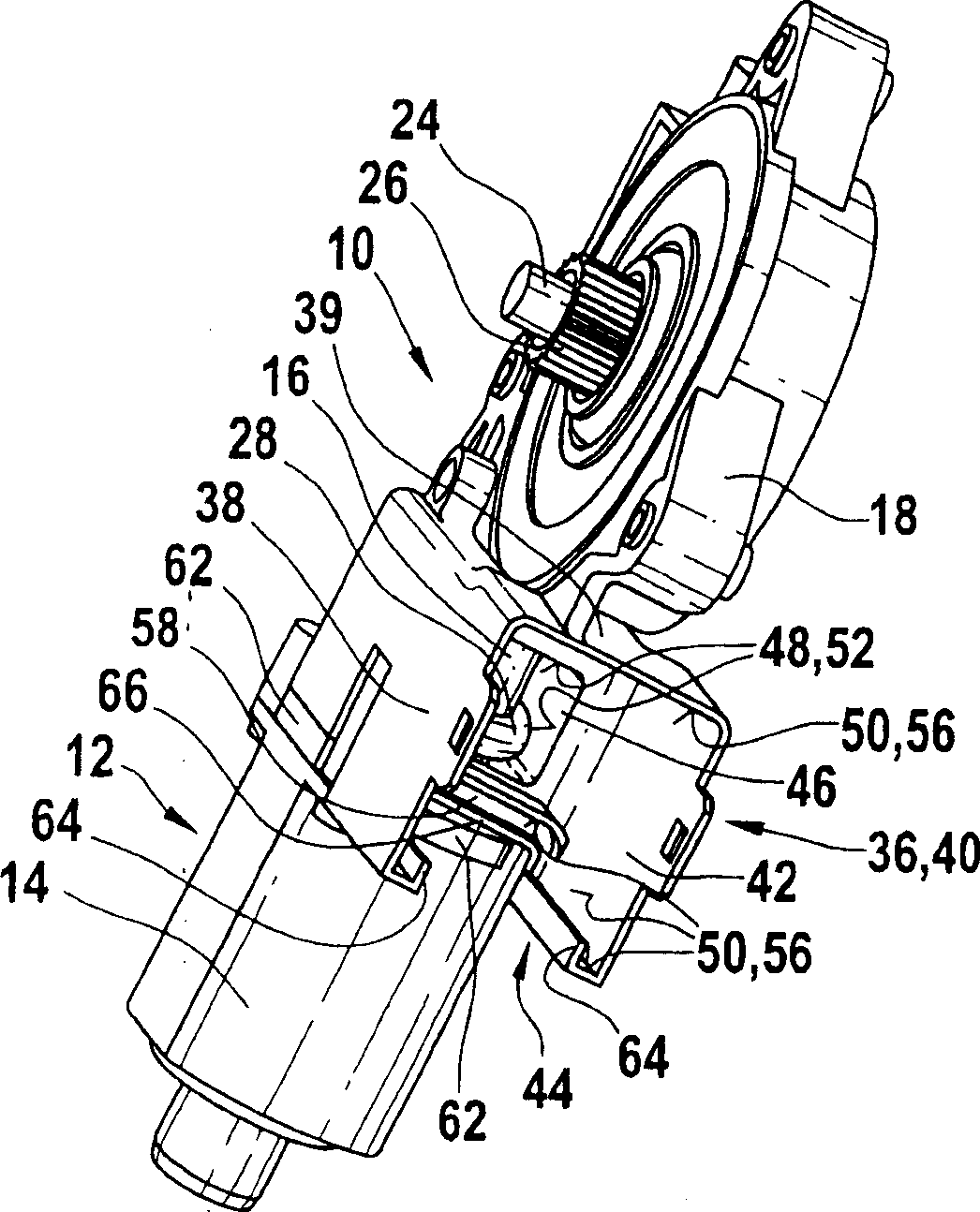
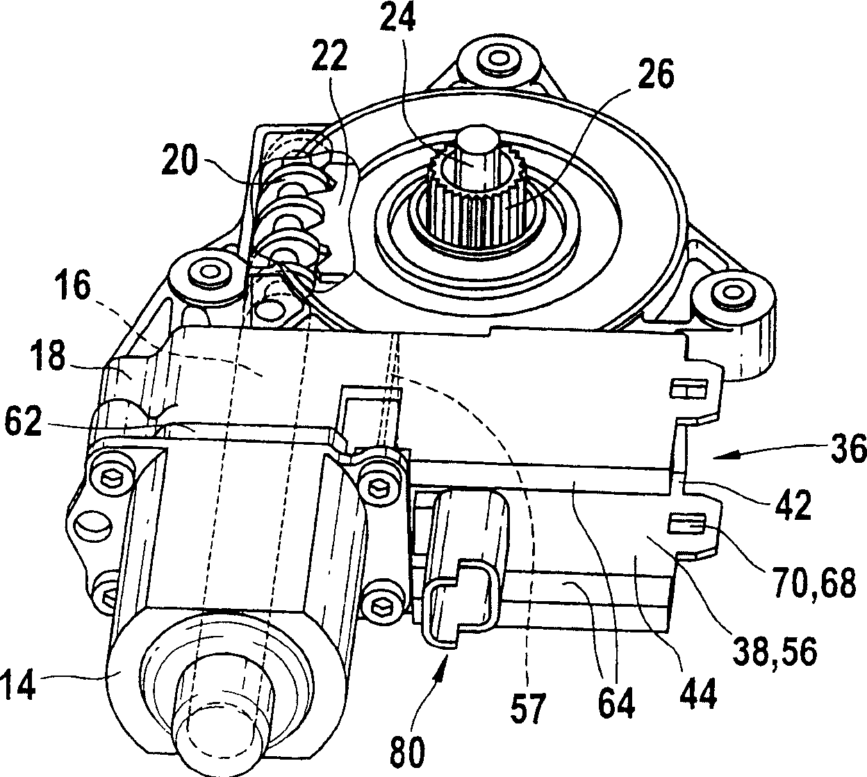
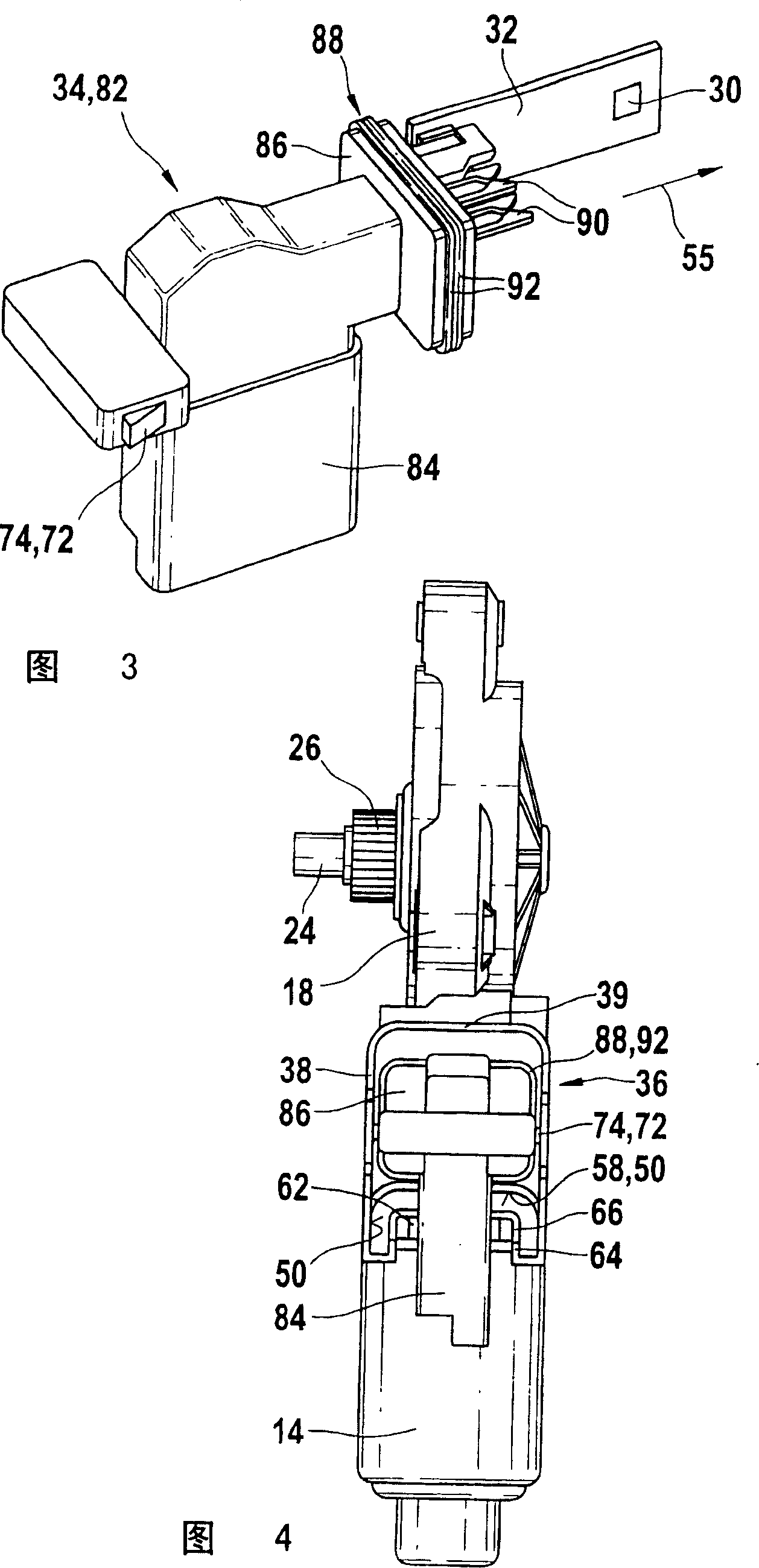
[0032] figure 1 It shows a speed reducer-drive unit 10 especially for a window regulator. The reducer-drive unit has an electric motor 12 housed in a pole shoe 14. The armature shaft 16 extends from the pole piece into the reducer case 18. A worm 20 is provided on the armature shaft 16, which meshes with the driven wheel 22, and transmits the force to an unshown window glass lifting mechanism through a transmission pinion 26 supported on the shaft 24 of the wheel . In order to detect the position of an adjustable part, a ring magnet 28 is provided, for example, on the armature shaft 16 in the area of ​​the reduction gear box 18. The ring magnet interacts with the Hall sensor 30 arranged on a printed circuit board of an insert module 34, 82, 110. In order to insert the plug-in module 34, the reducer-drive unit 10 has an electronic interface 36 which is integrally formed with one of the casing parts 16, 18, in this case and a reducer case 18 by means of a die-casting method. The el...


PUM


Abstract

Reducer-drive unit (10), which can be combined with different plug-in modules (34, 82, 94, 110), has an electric drive motor (12) with an armature shaft (16) and at least one receiving armature The casing part (18) of the shaft (16) and an electrical interface (36) for accommodating different plug-in modules (34, 82, 94, 110) which can be inserted into the electrical interface in the direction of insertion (55) (36), wherein the electronic interface (36) has walls (38) at a distance from each other, these walls form a hole (42) perpendicular to the armature shaft (16), axially along the armature shaft (16) A hole (44) is formed, and at least one first sealing surface (50) and guides (64) are provided on the wall (38) along the insertion direction (55) for different plug-in modules (34, 82, 94, 110) and sealing of at least one casing part (14, 18).

Description

Background technique [0001] The invention relates to a reducer-drive unit with an electronic interface according to the preamble of the independent claim. [0002] Different drive devices have been disclosed, in which a single electronic structural element can be coupled to a casing of the transmission device. For example, DE 200 04 338 A1 discloses a drive device with an electric motor in a reducer box, and an insert module can be inserted into the reducer box. The plug-in module has an end face, a plug is arranged on the outer side of the end face, a printed circuit board is arranged on the inner side of the end face, and electronic structural elements for motor power supply and motor contacts are arranged on the printed circuit board. An SMD Hall sensor is arranged on a pin of the printed circuit board, and the sensor works together with a ring magnet of the armature shaft when the sensor is installed. [0003] In addition, the end face of the plug-in module is provided with a ...

Claims


Application Information

Patent Timeline
Patent Type & Authority Applications(China)
IPC IPC(8): H02K11/00H02K5/22H02K7/116H02K29/08
CPCH02K5/225H02K7/1166H02K2211/03H02K11/20H02K11/215H02K11/38H02K7/116
Inventor T·胡克K·奥伯勒
Owner ROBERT BOSCH GMBH
Why Eureka
Try Eureka