Method for manufacturing sound boundary wave apparatus, and sound boundary wave apparatus

A manufacturing method and interface wave technology, applied in semiconductor devices, electrical components, impedance networks, etc., can solve problems such as moisture intrusion, and achieve excellent environmental resistance characteristics.

Inactive Publication Date: 2012-08-22
MURATA MFG CO LTD
View PDF1 Cites 0 Cited by
  • Summary
  • Abstract
  • Description
  • Claims
  • Application Information

AI Technical Summary

Problems solved by technology

Therefore, moisture or the like may intrude from the interface portion exposed on the side surface of the acoustic boundary wave element 501.

Method used


Image

  • Method for manufacturing sound boundary wave apparatus, and sound boundary wave apparatus
  • Method for manufacturing sound boundary wave apparatus, and sound boundary wave apparatus
  • Method for manufacturing sound boundary wave apparatus, and sound boundary wave apparatus

Examples


Embodiment Construction

[0051] Hereinafter, the present invention will be clarified by describing specific embodiments of the present invention with reference to the drawings.

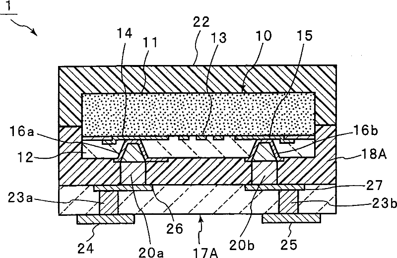
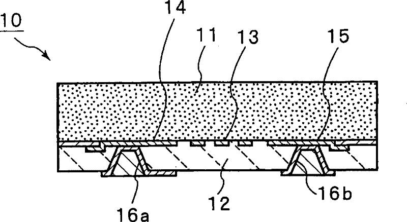
[0052] refer to Figure 1 ~ Figure 1 5. A method of manufacturing the boundary acoustic wave device according to the first embodiment of the present invention will be described.

[0053] first, prepare figure 2 The boundary acoustic wave element 10 is shown. The boundary acoustic wave element 10 has a structure in which a first dielectric layer 11 and a second dielectric layer 12 are laminated. In this embodiment, the first intermediary layer 11 is made of LiNbO 3 Piezoelectric single crystal substrates such as single crystal substrates. In addition, the first medium 11 may be formed of a piezoelectric material other than a piezoelectric single crystal.

[0054] In this embodiment, the second medium 12 is made of SiO 2 film formation, but the second medium 12 can also be made of SiO 2 Other dielectrics or insulators. ...


PUM


Abstract

This invention provides a method for manufacturing an elastic boundary wave apparatus in which an external terminal in an elastic boundary wave element and a part for electrically connecting the external terminal to the external are reliably reinforced, and, at the same time, the entry of moisture and the like through the interface of the first and second media in the elastic boundary wave element is less likely to take place. This method comprises the steps of providing a curing resin sheet in which at least one via hole electrode (20a, 20b) is provided so as to extend from one main plane tothe other main plane, providing an elastic boundary wave element (10) provided on one main plane of the curing resin sheet so that the external terminals (16a, 16b) in the elastic boundary wave element (10) are electrically connected to the via hole electrodes (20a, 20b), then pushing the elastic boundary wave element (10) into the curing resin sheet so that the curing resin sheet covers at leasta part, which appears on the outer surface of the boundary between the first and second media (11, 12) in the elastic boundary wave element (10), and then curing the curing resin sheet to prepare a resin sheet cured product (18).

Description

technical field [0001] The present invention relates to a method for manufacturing a boundary acoustic wave device and a boundary acoustic wave device using boundary acoustic waves propagating at the interface between a first medium and a second medium, and more specifically, to an improved boundary acoustic wave element product A method of manufacturing a boundary acoustic wave device with an optimized structure and a boundary acoustic wave device. Background technique [0002] Conventionally, various surface acoustic wave devices have been used in RF filters for mobile phones, resonators for VCOs, VIF filters for television receivers, and the like. On the other hand, the boundary acoustic wave device has attracted attention because it can not only simplify the package structure but also promote miniaturization compared with the surface acoustic wave. [0003] For example, in the following patent document 1, a Figure 12 The BAW component shown. In the boundary acoustic w...

Claims


Application Information

Patent Timeline
Patent Type & Authority Patents(China)
IPC IPC(8): H03H3/08H03H9/25
CPCH03H9/0222H03H9/09H03H9/059H03H9/1085H01L2924/181
Inventor 小田哲也
Owner MURATA MFG CO LTD
Why Eureka
Try Eureka