

Formwork member molding die
A formwork component and forming mold technology, which is applied in the direction of formwork/formwork components, building components, formwork/formwork/work frame connectors, etc., can solve the problem of inconvenient demoulding, thin-walled pipes or thin-walled openings The box is easy to break and other problems
Inactive Publication Date: 2008-11-19
湖南邱则有专利战略策划有限公司
View PDF2 Cites 2 Cited by
- Summary
- Abstract
- Description
- Claims
- Application Information
AI Technical Summary
Problems solved by technology
Such as the female mold, as can be seen from their drawings, it includes a side mold surface and a bottom mold surface, and the side mold surface and the bottom mold surface form a female mold. This kind of female mold is the female mold of the overall template. In this case, it is inconvenient to demould, and the open thin-walled tube or thin-walled box is easily damaged. Therefore, it is urgent to develop a new type of mold for forming shell components.
Method used
View moreImage
Smart ImageViewing Examples

Examples
Embodiment Construction
Login to View More PUM
 Abstract
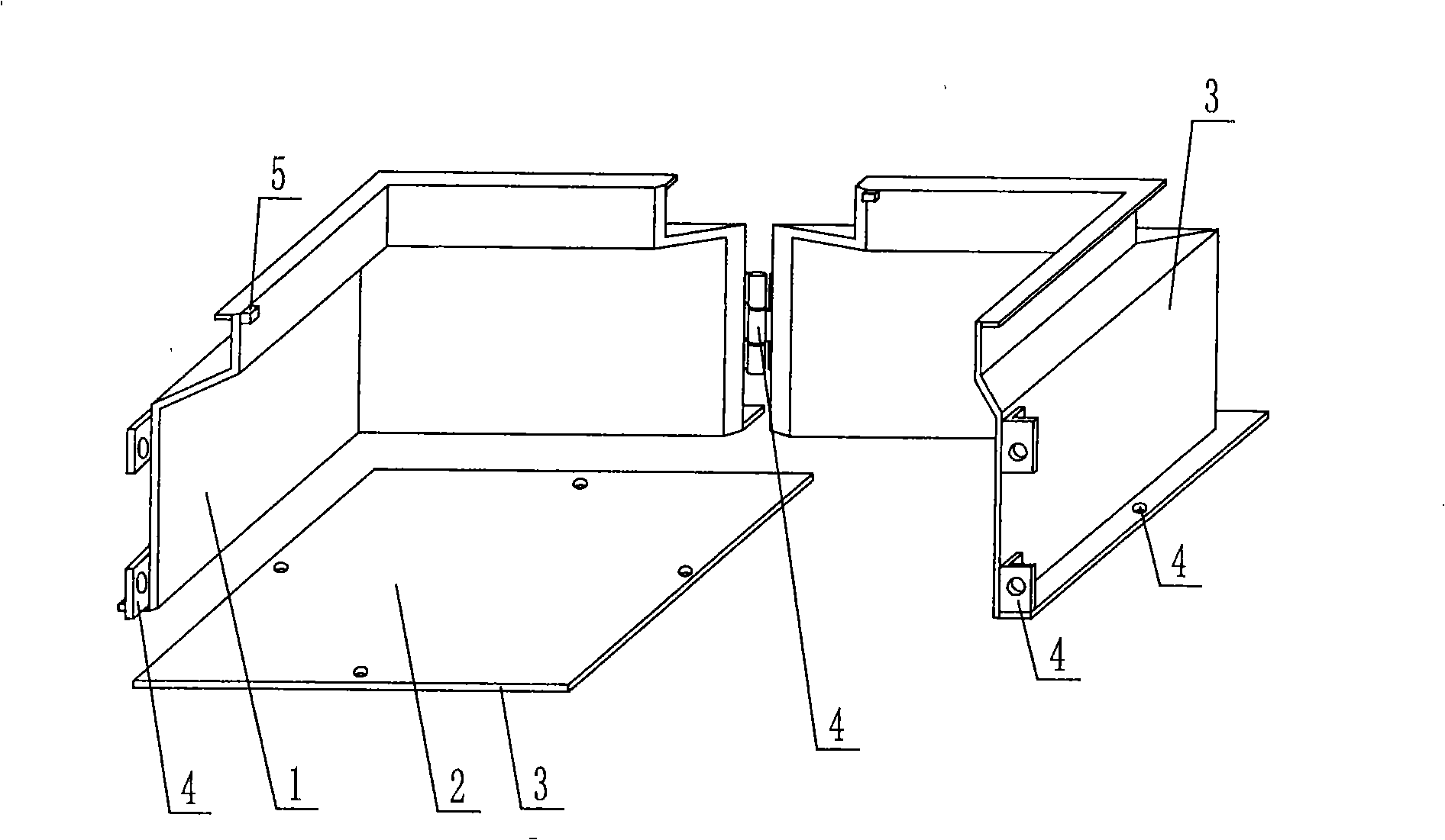
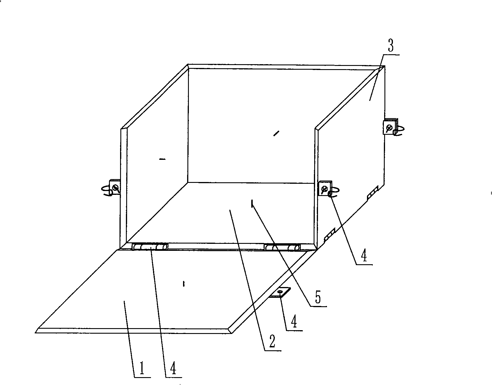
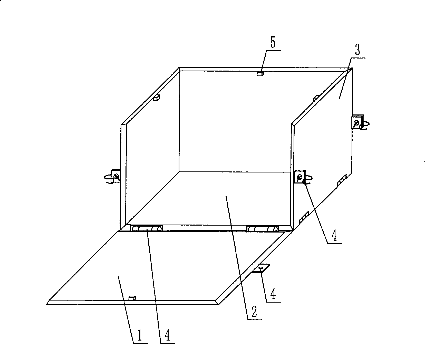
The invention relates to a formwork element mould, which comprises a side modular surface (1) and a bottom modular surface (2), wherein, the side modular surface (1) and the bottom modular surface (2) are enclosed into a female mould. The formwork element mould is characterized in that: the side modular surface (1) and the bottom modular surface (2) of the female mould are formed by formworks (3); the female mould is formed by joining together at least two formworks (3); joining devices (4) are arranged on the joined formworks (3); formwork thickness limit devices (5) are arranged on the formworks (3); the side modular surface (1) is formed by four formworks (3); and at least one gap (15) is arranged on each formwork (3) of the side modular surface (1). Therefore, after notches are arranged on the formworks, reinforces such as reinforcing steel bars, steel wires and so on can be very conveniently placed and positioned, thereby the formwork element mould is favorable for improving the production efficiency. Moreover, the mould is also characterized by simple structure, easy manufacture, high strength, low cost and so on, is suitable for manufacturing a thin-wall pipe or a thin-wall box and particularly suitable for manufacturing an opened thin-wall pipe or an opened thin-wall box.
Description
Forming mold for a formwork component This application is a divisional application of the invention patent application with the filing date of January 20, 2004, the application number of 200410002653.X, and the title of "a mold for molding shell components". (1) Technical field The invention relates to a mold for forming a mold shell component. (2) Background technology At present, cast-in-place reinforced concrete hollow slabs, especially the non-core-pulling hole-forming process of cast-in-situ reinforced concrete hollow slabs, are generally filled with thin-walled tubes or thin-walled boxes, which can meet the needs of various hollow slabs for evacuating concrete. The applicant applied for an invention patent with the application number 99115665.X and the title "fiber-reinforced thin-walled pipe (box) for reinforced concrete filling and its manufacturing method" on November 29, 1999, and the application number 99115666.8 , the invention patent titled "fiber-reinforced...
Claims
Login to View More Application Information
Patent Timeline
 Patent Type & AuthorityApplications(China)
IPC IPC(8): E04G9/08E04G17/00E04B5/16
Inventor邱则有
Owner湖南邱则有专利战略策划有限公司