Refrigerant system possessing multi- speed cyclone compressor and economizer loop

A refrigerant system, scroll compressor technology, applied in irreversible cycle compressors, compressors, refrigerators, etc.

Inactive Publication Date: 2008-11-19
SCROLL TECH
View PDF1 Cites 18 Cited by
  • Summary
  • Abstract
  • Description
  • Claims
  • Application Information

AI Technical Summary

Problems solved by technology

[0008] However, scroll compressors have not been used in conjunction with a two-speed drive fo

Method used


Image

  • Refrigerant system possessing multi- speed cyclone compressor and economizer loop
  • Refrigerant system possessing multi- speed cyclone compressor and economizer loop

Examples


Embodiment Construction

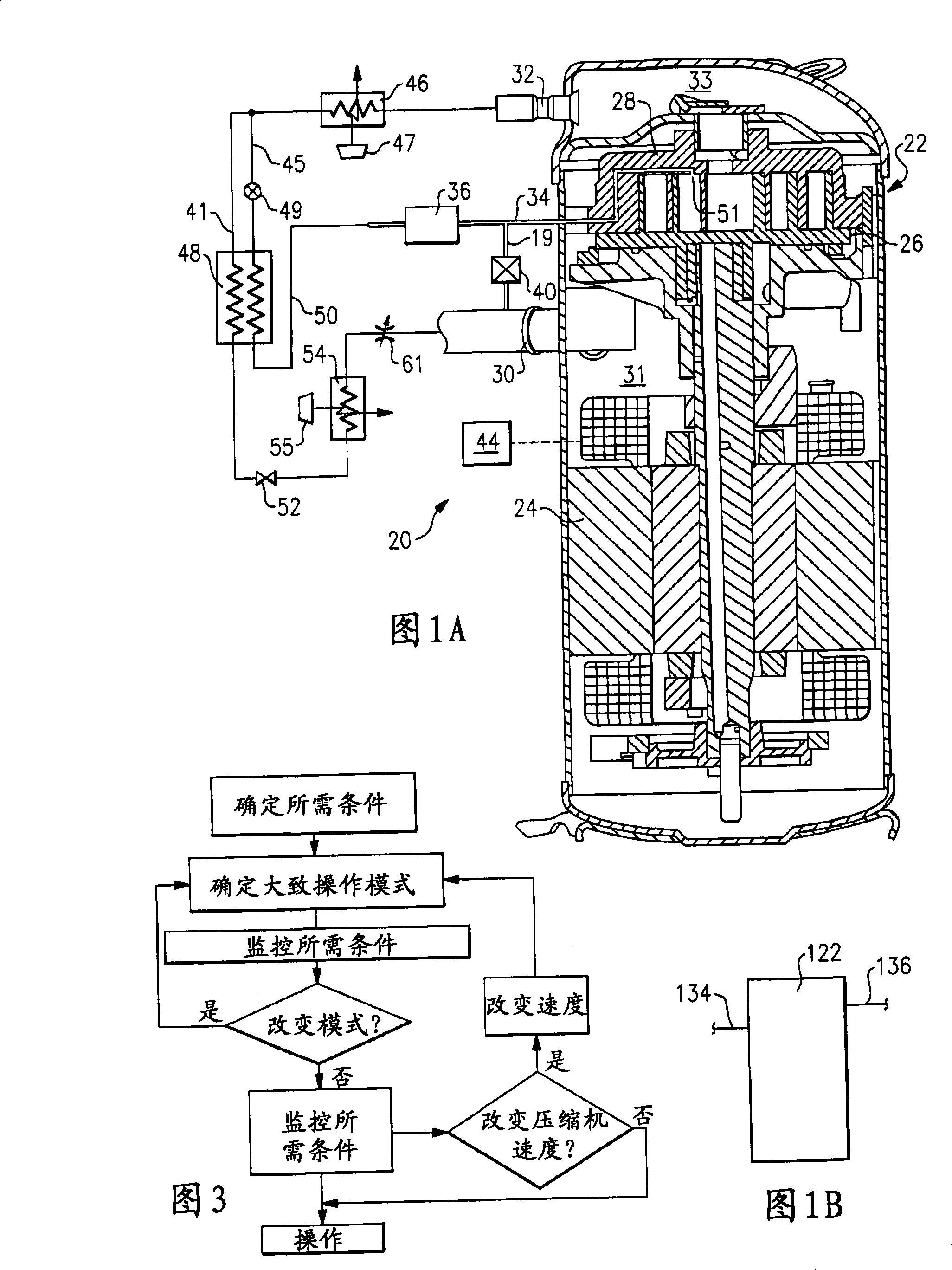
[0018] The refrigerant system 20 is shown in FIG. 1A , the refrigerant system 20 has a compressor 22 and a controller 44 . As is known, the motor 24 for the compressor 22 can be driven at two speeds so that the amount of refrigerant compressed by the compressor 22 and circulated throughout the system can be varied. That is, the compressor is driven at one of two non-zero speeds during steady state operation. The compressor 22 is a scroll compressor having an orbiting scroll member 26 and a non-orbiting scroll member 28 . As is known, a plurality of compression pockets are defined between the two scroll members, which compress entrained refrigerant when the orbiting scroll member 26 is driven to orbit by the motor 24 . It can be seen that the suction pipe 30 leads the refrigerant into the suction chamber 31 surrounding the motor and opening into the compression chamber. When the refrigerant is compressed, it is driven into the discharge chamber 33 which communicates with the ...


PUM


Abstract

The invention relates to a scroll compressor, which is provided with a multi-speed motor. A controller selectively controls the speed of the motor; and simultaneously a plurality of realizable alternative proposals selectively adjust system capacity so as to meet the requirement of external load in the most efficient and reliable mode. The embodiment comprises an economizer circuit and emptier function and an alternative input control valve. Various parts of the multi-speed motor of the compressor are used, so the capacity provided by the compressor is more suitable for the required capacity.

Description

technical field [0001] The present invention relates to a two-speed scroll compressor operating in a refrigerant system, the scroll compressor having an economizer function and other capacity adjustment devices. Background technique [0002] Refrigerant systems are used in a variety of applications to condition the environment. In particular, air conditioners and heat pumps are employed to cool and / or heat secondary fluids such as air entering the environment. The cooling or heating load of the environment may vary according to ambient conditions, occupancy levels, changes in other sensible and latent heat load demands, and temperature and / or humidity setpoint adjustments by building occupants. [0003] Thus, refrigerant systems may be provided with complex controllers, and multiple optional components and components to regulate cooling and / or heating capacity. Known options include the ability to bypass at least part of the refrigerant compressed by the compressor back in...

Claims


Application Information

Patent Timeline
IPC IPC(8): F25B1/00F25B40/06F04C18/02F04C28/24
Inventor A·利夫森M·F·塔拉斯
Owner SCROLL TECH
Why Eureka
Try Eureka