Method and apparatus for realizing power control and method for managing neighbor list

A technology of power control and neighbor list, applied in transmission control/equalization, data exchange through path configuration, advanced technology, etc., can solve the problem of not guaranteeing network connectivity throughput, reduce channel space reuse, and communication collision rate increase, etc.

Inactive Publication Date: 2008-11-19
SHENZHEN INST OF ADVANCED TECH
View PDF0 Cites 15 Cited by
  • Summary
  • Abstract
  • Description
  • Claims
  • Application Information

AI Technical Summary

Problems solved by technology

[0004] If the fixed transmission power is set too high, the energy of the nodes will undoubtedly be wasted, and to a certain extent, mutual interference between nodes will be caused, reducing the spatial multiplexing of the

Method used


Image

  • Method and apparatus for realizing power control and method for managing neighbor list
  • Method and apparatus for realizing power control and method for managing neighbor list
  • Method and apparatus for realizing power control and method for managing neighbor list

Examples


Embodiment approach

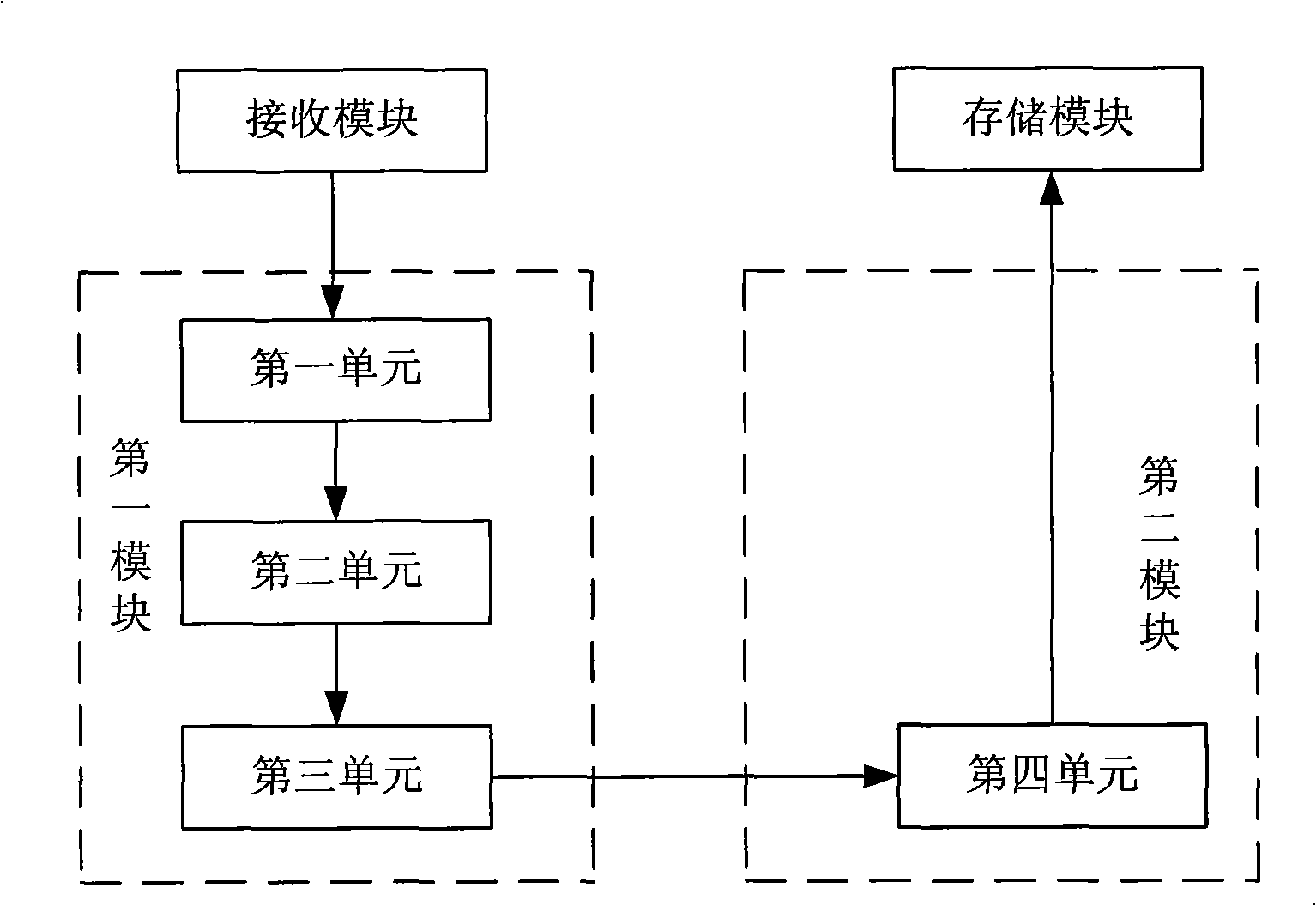
[0060] This device has following two kinds of specific implementation modes, one, as figure 2 Shown:

[0061] The first module includes: a first unit connected to the receiving module, configured to acquire the perceived signal strength of the node; a second unit connected to the first unit, configured to The minimum sensitivity of the node and the value of the transmission power calculate the minimum transmission power of the node; the third unit connected to the source node is used to feed back the minimum transmission power to the source node;

[0062] The second module includes: a fourth unit connected to the third unit and the storage module, configured to find a maximum value among multiple minimum transmission powers, and assign the maximum value to the transmission power.

[0063] In this specific embodiment, the second unit for calculating the minimum transmission power is set in the first module on the destination node.

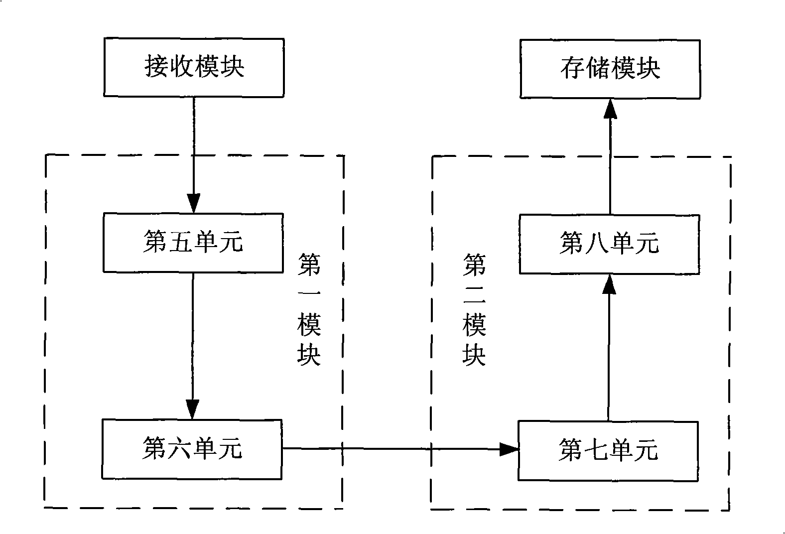
[0064] Second, if image 3 Shown:

[006...

specific Embodiment approach

[0077] One: when the correction information is the minimum transmission power, that is, the calculation of the minimum transmission power is completed by the target node, step 500 includes the following steps:

[0078] 510. When the target node receives the information packet, acquire the perceived signal strength;

[0079] 520. The target node calculates the minimum transmit power of the node according to the perceived signal strength of the node, the minimum sensitivity, and the value of the transmit power, and feeds it back to the source node;

[0080] 530. The source node adds the target node to the neighbor list, and grants the minimum transmission power to the transmission power.

[0081] Second: the correction information includes the perceived signal strength and minimum sensitivity of the target node, that is, the calculation of the minimum transmission power is completed by the source node, and step 500 includes the following steps:

[0082]510'. When the target nod...


PUM


Abstract

The invention discloses a method which can realize power control and the device thereof, and a method to manage the neighbor list. Wherein, the device to realize power control includes a transmitting module arranged at the source node to transmit a power transmitting information packet which has the value of the transmitting power, a storage module arranged at the source node and connected with the transmitting module to store the power transmitting information, and a receiving module arranged at the destination node and connected with the transmitting module to receive the information packet. The device also includes a first module arranged at the destination node and connected with the receiving module for obtaining the modification information according to the value of the transmitting power, a second module arranged at the source node and connected with the first module and the storage module for modifying the transmitting power according to the modification information. Adopting the device can save energy and increase the communication channel space reuse degree while at the same time keeps the network a fine connectivity by the nodes in the wireless sensor network.

Description

technical field [0001] The present invention relates to a method and system for transmitting measured values, control signals or similar signals, in particular to a method and device for distributed power control in a wireless sensor network and a method for managing a neighbor list. Background technique [0002] Wireless sensor network is a self-organizing and energy-constrained wireless network technology, which relies on sensor nodes to collect information and transmit it back to the base station through wireless multi-hop. Due to the limitation of size and cost, sensor nodes usually use batteries with limited energy to provide energy. Due to the large number of nodes in the entire network and their wide distribution, the working environment is usually relatively harsh. It is very difficult to charge or replace the batteries of nodes. Therefore, Controlling energy consumption plays an extremely important role in sensor networks. The energy-consuming modules of sensor nod...

Claims


Application Information

Patent Timeline
IPC IPC(8): H04B7/005H04L12/28
CPCY02B60/50Y02D30/70
Inventor 肖坚陶利强于峰崎
Owner SHENZHEN INST OF ADVANCED TECH
Why Eureka
Try Eureka