Current source, control device and method for operating said control device

A technology of power supply and piezoelectric actuator, applied in electrical control, engine control, fuel injection control, etc., can solve problems such as short response time, and achieve the effect of low cost and simple adjustment characteristics

Active Publication Date: 2011-04-13
VTESCO TECH GMBH
View PDF0 Cites 0 Cited by
  • Summary
  • Abstract
  • Description
  • Claims
  • Application Information

AI Technical Summary

Problems solved by technology

Piezo actuators are characterized by extremely short response times

Method used


Image

  • Current source, control device and method for operating said control device
  • Current source, control device and method for operating said control device
  • Current source, control device and method for operating said control device

Examples


Embodiment Construction

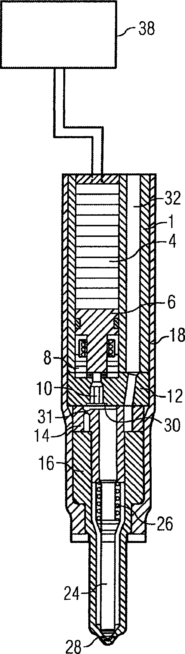
[0022] Injection valve ( figure 1 ) has an injector housing 1 which has a recess into which the piezo actuator PAKT1 coupled to the transmitter 6 (ie the piezo actuator) is inserted. The conveyor 6 is arranged in the leakage space 8 . The switching valve 10 , which is preferably designed as a servo valve, is arranged such that it controls a leakage fluid, which in this embodiment is preferably fuel, as a function of its switching position. The switching valve is coupled via the transmitter 6 to the piezo actuator PAKT1 and is driven by it, ie the switching position of the switching valve 10 is set by means of the piezo actuator PAKT1 . If necessary, piezo actuator PAKT1 can also act on switching valve 10 without intermediary transmitter 6 . The switching valve 10 is arranged in a valve plate 12 . The on-off valve 10 comprises a valve element whose position can be adjusted by means of a piezo actuator PAKT1 and which, in a switching position, is in contact with the valve pla...


PUM


Abstract

The invention relates to a current source comprising a first switching element (T1), which has a control input (54) and is designed to adjust an output current (I_A) in accordance with a control signal that is received by said control input (54). The current source also comprises a reference resistance (R_S), which is electrically coupled to the first switching element (T1) in such a way that theoutput current (I_A) flows through the reference resistance (R_S). The latter (R_S) comprises first and second individual reference resistances (R5, R6), which are arranged in series and a diode (D1)that is connected in parallel to the first individual reference resistance (R5). The first individual reference resistance (R5) has a higher impedance than the second individual reference resistance (R6).; The power source is equipped with a controller (52), to which a predetermined reference potential (U_REF) is fed and whose actuating signal constitutes the control signal of the first switchingelement (T1). A second switching element (T2) is configured to supply the controller (52) with an actual value consisting of the voltage across between the first and second individual reference resistances (R5, R6), when the element adopts a first switching position and consisting of the voltage drop across the second individual reference resistance (R6), when the element adopts a second switching position.

Description

technical field [0001] The invention relates to a power supply, a control device and a method for operating the control device, in particular for piezoelectric actuators. Background technique [0002] Increasingly stringent legal regulations regarding the permissible emission of pollutants from internal combustion engines arranged in motor vehicles make it necessary to take various measures by which the emission of pollutants is reduced. The starting point in this case is to reduce the pollutant emissions produced during the combustion process of the air / fuel mixture. In particular the formation of soot is strongly dependent on the preparation of the air / fuel mixture in the corresponding cylinders of the internal combustion engine. In order to achieve a very good mixture preparation, the fuel is increasingly dispensed at very high pressure. In the case of diesel internal combustion engines the fuel pressure is up to 2000 bar. Injection valves with piezoelectric actuators ...

Claims


Application Information

Patent Timeline
Patent Type & Authority Patents(China)
IPC IPC(8): H01L41/04F02D41/20
CPCF02D2041/2058H02N2/067F02D41/2096F02D41/20H10N30/80
Inventor M·格岑贝尔格
Owner VTESCO TECH GMBH
Why Eureka
Try Eureka