Optical fiber connector

A fiber optic connector and connector technology, applied in the direction of instruments, optics, light guides, etc., can solve problems such as stress concentration, optical signal bending loss, main cladding damage, etc., and achieve the effects of preventing cracking, reliable protection, and avoiding stress concentration

Inactive Publication Date: 2008-11-19
3M INNOVATIVE PROPERTIES CO +1
View PDF1 Cites 1 Cited by
  • Summary
  • Abstract
  • Description
  • Claims
  • Application Information

AI Technical Summary

Problems solved by technology

[0008] However, since the boundary 32 of the optical fiber core 31 has a step in which the diameter changes, if the main cladding portion 31 is bent inside the connector 30, there is a risk of stress concentration at the boundary 32, resulting in bending loss of the optical signal or breakage of the main cladding portion.

Method used


Image

  • Optical fiber connector
  • Optical fiber connector
  • Optical fiber connector

Examples


Embodiment Construction

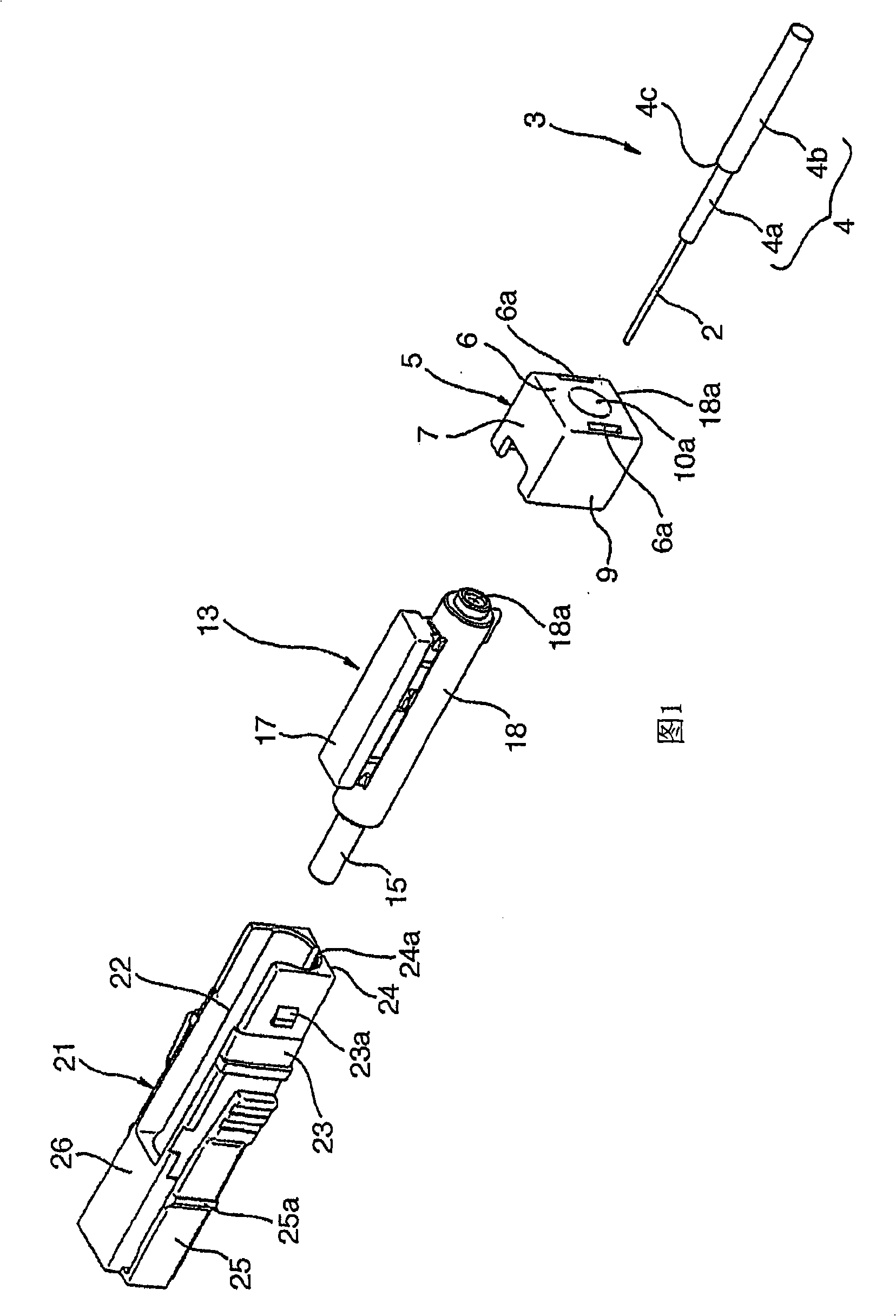
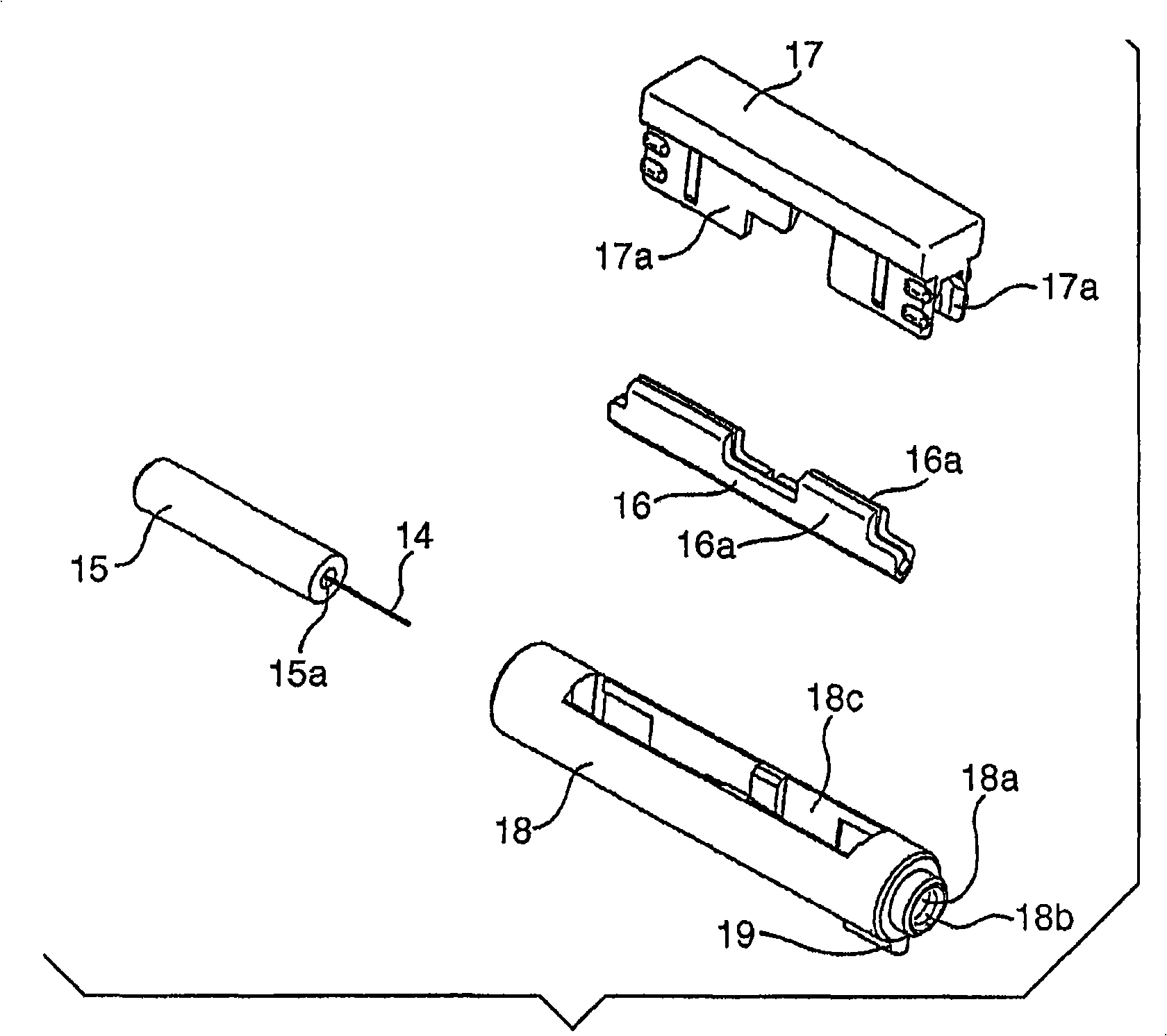
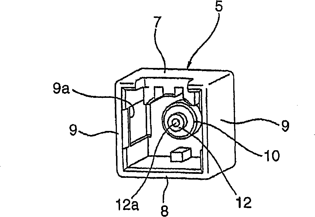
[0025] Preferred embodiments of the present invention will be described in detail below with reference to the accompanying drawings. Figure 1 is an exploded perspective view of one embodiment of the fiber optic connector of the present invention. According to this embodiment, the optical fiber connector 1 includes: a main cladding part 3 formed by covering the outer circumference of the bare optical fiber part 2 with a layered structure inner cladding 4; Cover 5; a splice assembly 13 for adjoining the end face of the bare optical fiber portion 2 and optically connecting thereto; Engaged connector housing 21 .

[0026] The main cladding part 3 is formed by removing the thick outer covering of its cladding from the optical fiber cable, which consists of a bare optical fiber part (glass optical fiber) and an inner covering 4 of a multilayer structure covering the optical fiber . The inner cover member 4 of a multilayer structure is formed by a method of repeatedly using a resi...


PUM


Abstract

The optical fiber connector includes a connector housing (21), having a splice assembly (13) therein, and an end cap (5) attached to one end of the connector housing (21), from which leads out a primary coating portion (3). A boundary (4c) between a portion of the primary coating portion (3), obtained by removing an outer coating (4b) of the inner cover (4) while leaving an inner coating (4a), and a portion obtained by leaving the outer coating (4b) of the inner cover (4), is located in the interior of the connector housing (21). The end cap (5) is provided in the interior thereof with a tubular portion and an extension extending from an end of the tubular portion, the tubular portion including an insert hole for an insertion of the primary coating portion (3) approximately coaxially with a guiding hole formed in the splice assembly accommodated in the connector housing (21) for guiding the primary coating portion (3) leading out from the splice assembly. The extension includes a strain-control hole, communicating with the insert hole, for receiving said boundary (4c) of the primary coating portion (3), and for controlling stress at the boundary (4c).

Description

technical field [0001] The present invention relates to an optical fiber connector having a splice assembly therein for optically joining together end faces of bare fiber optic portions, each end face of which has had a fiber optic cable cover removed, while the end faces abut each other. Background technique [0002] Generally, as disclosed in Japanese Patent No. 3445479, an optical fiber connector has a splice assembly for optically connecting the end faces of bare optical fiber portions while making the end faces abut each other. With the fiber optic cable cover removed, the fiber optic connectors have been routinely used in the workplace to easily interconnect fiber optic cables. [0003] Japanese Patent No. 3445479 discloses a so-called mechanical splice type fiber optic connector comprising a splice assembly for securing a ferrule having a main cladding portion and a splice extending from the rear end surface of the ferrule. An extension of the primary cladding portio...

Claims


Application Information

Patent Timeline
Patent Type & Authority Applications(China)
IPC IPC(8): G02B6/36
CPCG02B6/3846G02B6/3887G02B6/38875G02B6/36
Inventor 矢崎明彦山内孝哉大池知保丰永正宣寺川邦明棚濑弘幸中岛达也粟森正志
Owner 3M INNOVATIVE PROPERTIES CO
Why Eureka
Try Eureka