
Method for cable theft prevention, terminal and system

A terminal and cable technology, which is applied in the field of cable anti-theft, can solve the problems of high cost, stolen cables, and easy damage to anti-theft equipment, and achieve the effect of low cost and low cost, and solve the effect of cable anti-theft

Inactive Publication Date: 2008-11-26
魏建才
View PDF0 Cites 6 Cited by
  • Summary
  • Abstract
  • Description
  • Claims
  • Application Information

AI Technical Summary

Problems solved by technology

[0004] However, in practical application, this technology requires a steel wire with the same length as the cable, and the cost is high; although the steel wire is difficult to be destroyed, there is still a corresponding cracking method, that is to say, the anti-theft device itself is easy to be destroyed
Therefore, the prior art does not fundamentally solve the problem of cable theft

Method used


Image

  • Method for cable theft prevention, terminal and system
  • Method for cable theft prevention, terminal and system
  • Method for cable theft prevention, terminal and system

Examples


Embodiment 1

[0055] In this embodiment, the signal transmitting device is a GPS satellite, the terminal is a GPS terminal, and the terminal communicates with the monitoring server through a base station of a wireless communication network.

[0056] GPS technology is a technology that uses GPS satellites for precise positioning. It has the advantages of high positioning accuracy, short positioning time, and three-dimensional coordinates.

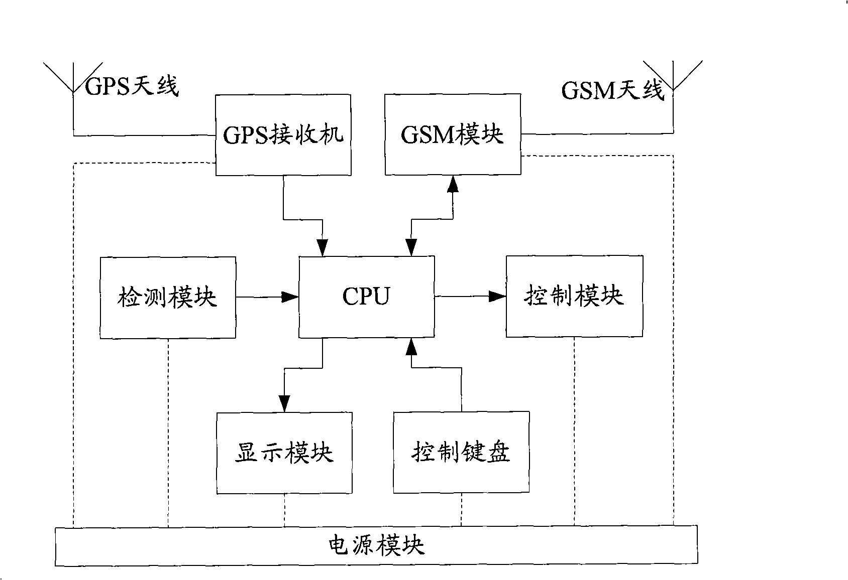
[0057] image 3 It is a structural schematic diagram of an existing GPS terminal. see image 3 , the existing GPS terminal includes a GPS antenna, a GSM antenna, a GPS receiver, a GSM module, a detection module, a control module, a display module, a control keyboard, a power supply module and a central processing unit (CPU, Central Processing Unit).

[0058] Wherein, the GPS receiver receives the signal from the GPS satellite through the GPS antenna, measures the transmission time of the signal, and transmits it to the CPU.

[0059] The CPU measures th...

Embodiment 2

[0082] In this embodiment, the signal transmitting device is a base station, and the terminal is a wireless terminal fixed in a cable.

[0083] Figure 6 It is a structural schematic diagram of the wireless terminal used for cable theft prevention according to the present invention. see Figure 6 , the wireless terminal includes a wireless communication antenna, a wireless communication module, a CPU and a power supply module.

[0084] Wherein, the wireless communication module is used to receive wireless signals from at least one base station through a wireless communication antenna and transmit them to the CPU; receive data information transmitted by the CPU and send them to the monitoring server.

[0085] The CPU is used to measure the transmission time of the wireless signal from each base station to the wireless communication module, generate data information including the pre-saved terminal identification, the location information of the base station and the correspond...


PUM


Abstract

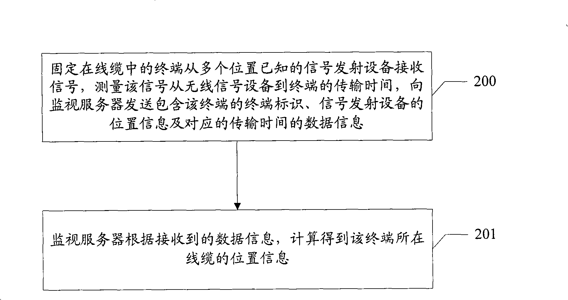
The invention discloses an anti-theft method for wire cables, comprising: a terminal fixed in the wire cables receives signals from at least a location-known signal emission device, the signal transmission time from the signal emission device to the terminal is measured, and the data information including the terminal identification of the terminal, the location information of the signal emission device and the corresponding transmission time are transmitted to a monitoring server; the monitoring server successfully measures and obtains the location information of the cable wire where the terminal locates according to the data information received. The invention also discloses a terminal and a system used for wire cable anti-theft. With the method of the invention, the location information of all the wire cables with the terminal fixed can be obtained, so that the monitoring staff can be automatically informed of when the wire cables are being stolen. Therefore, the monitoring staff can monitor and track the stolen wire cables, thus ensuring that under the low cost premise, the wire cable anti-theft can be realized and the difficult problem in the field of wire cable anti-theft is solved.

Description

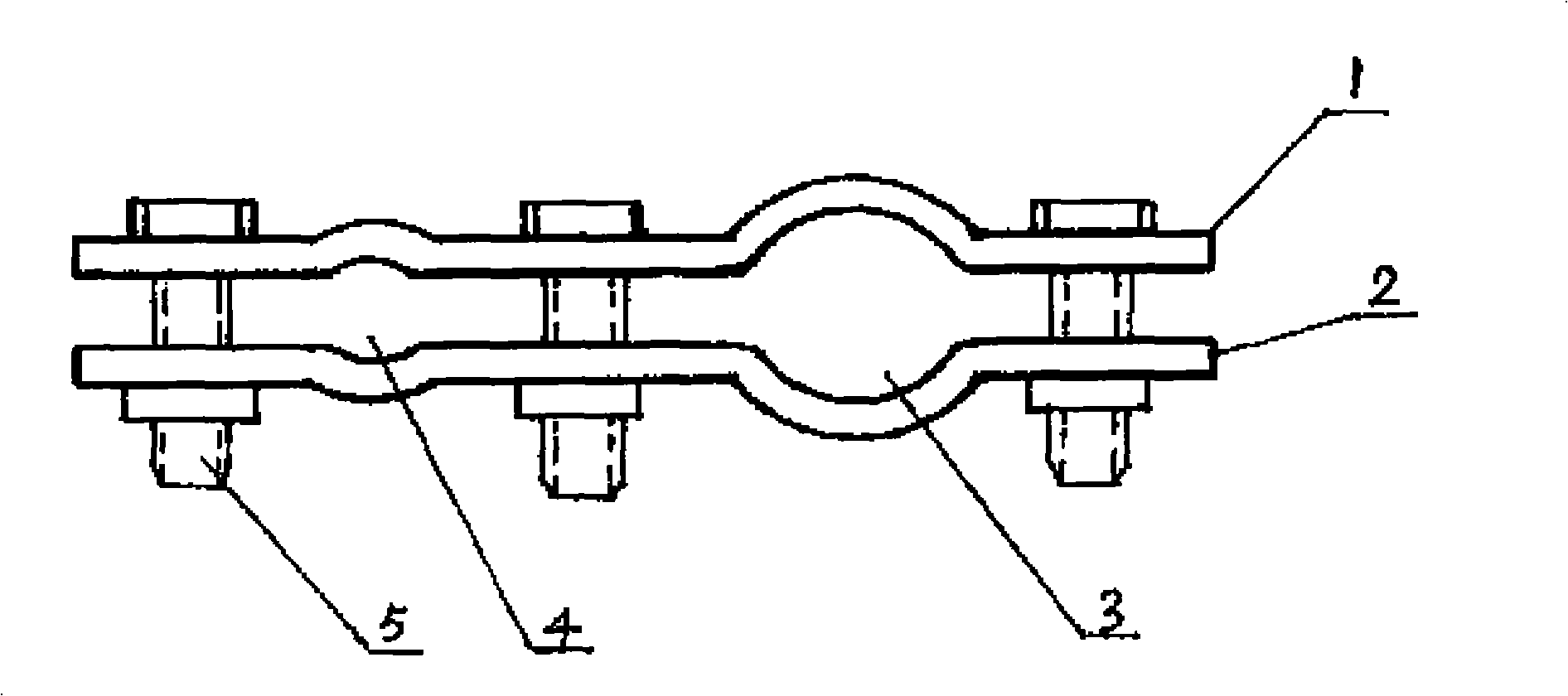
technical field [0001] The invention relates to anti-theft technology, in particular to a method, terminal and system for cable anti-theft. Background technique [0002] With the development of science, technology and economy, communications are playing an increasingly vital role in daily life and social production. However, the phenomenon of stealing communication cables is becoming more and more serious throughout the country, seriously damaging the communication network of our country and causing immeasurable losses to the country and the people. [0003] figure 1 For the existing anti-theft card board used for communication cable anti-theft, see figure 1 , the anti-theft cardboard includes an upper cardboard 1 and a lower cardboard 2 with two arc arched surfaces. The contact surfaces of the upper clamping plate 1 and the lower clamping plate 2 form a cable hole 3 and a steel wire hole 4, which are connected by fastening bolts 5, so that the communication cable inserte...

Claims


Application Information

Patent Timeline
Patent Type & Authority Applications(China)
IPC IPC(8): G08B13/00G08B13/12G08B25/00G08B25/10
Inventor 魏建才
Owner 魏建才
Learn More