Antenna carrier structure and antenna apparatus possessing antenna carrier structure

A technology of bracket structure and antenna device, which is applied in the direction of antenna support/mounting device, antenna, fixed connection, etc., and can solve the problems of bad contact between printed circuit board and micro antenna, inconvenient use, insufficient support strength, etc.

A technology of bracket structure and antenna device, which is applied in the direction of antenna support/mounting device, antenna, fixed connection, etc., and can solve the problems of bad contact between printed circuit board and micro antenna, inconvenient use, insufficient support strength, etc.

CN101312264AActive Publication Date: 2008-11-26INPAQ TECH

Image

  • Antenna carrier structure and antenna apparatus possessing antenna carrier structure
  • Antenna carrier structure and antenna apparatus possessing antenna carrier structure
  • Antenna carrier structure and antenna apparatus possessing antenna carrier structure

Examples


Embodiment Construction

[0043] In order to further understand the features and technical content of the present invention, please refer to the following detailed description of the present invention and the accompanying drawings.

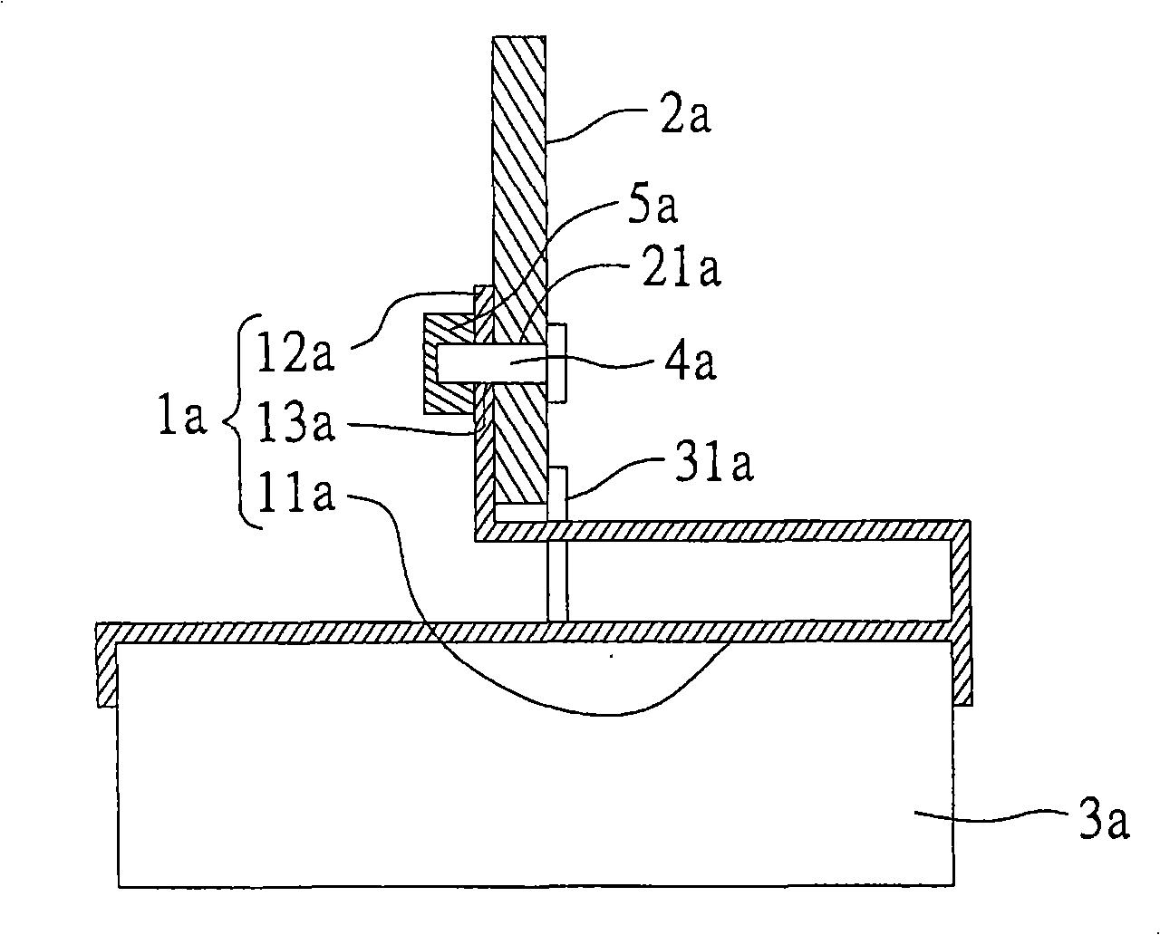
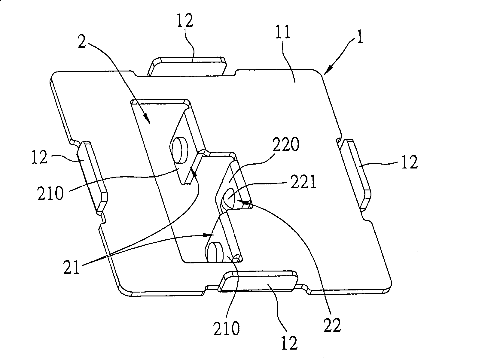
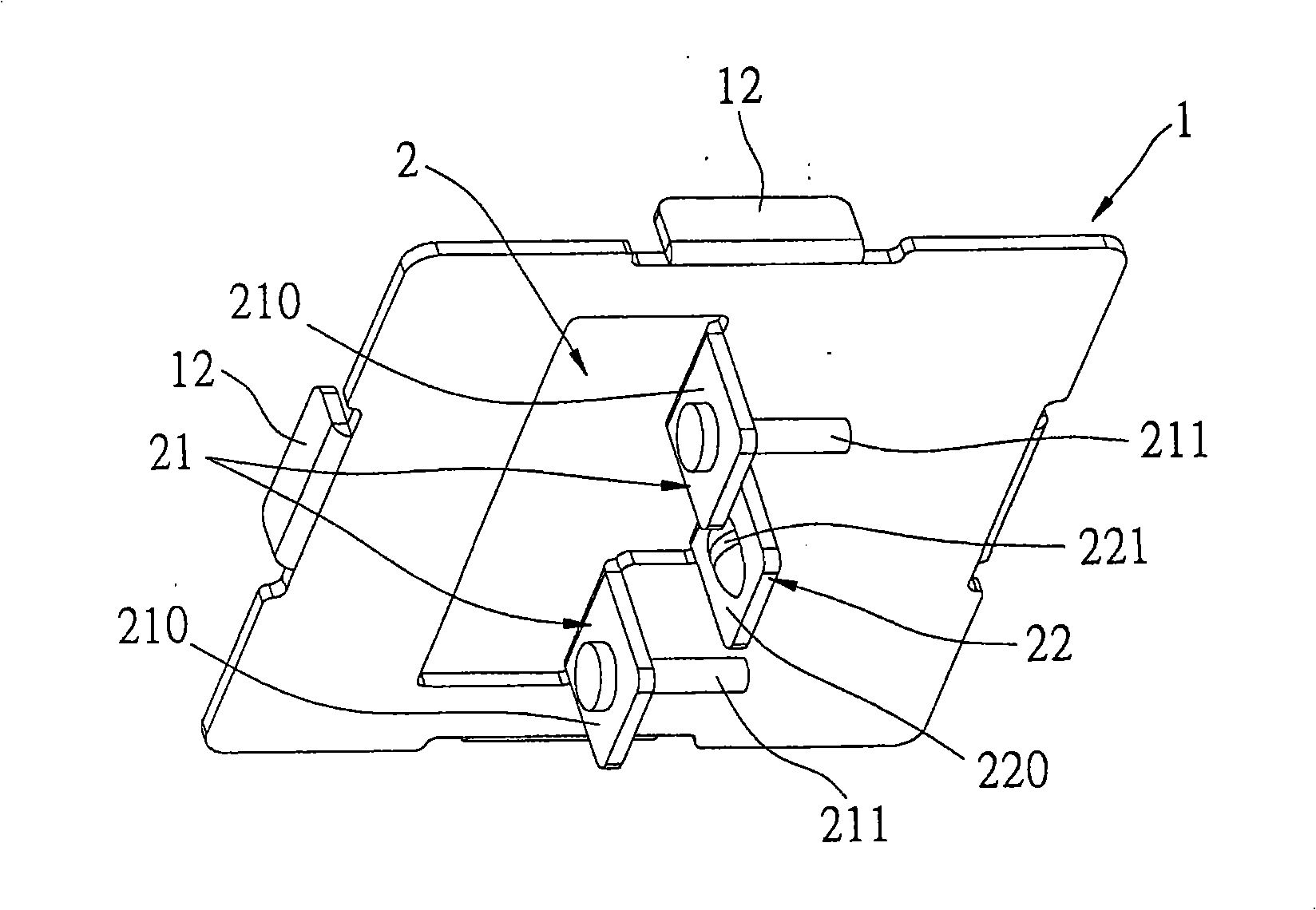
[0044] see Figure 2 to Figure 5 As shown, it is an embodiment of the antenna bracket structure of the present invention. It is known from the figure that the antenna bracket structure includes: an antenna bracket 1 and a positioning and fastening unit 2, and the positioning and fastening unit 2 Formed on the antenna bracket 1, and the positioning and fastening unit 2 has a positioning portion 21 and a fastening portion 22 cooperating with the positioning portion 21;

[0045] Thereby, the present invention can utilize the cooperation between the positioning portion 21 and the fastening portion 22, so that the antenna bracket 1 can be stably electrically connected to a circuit board (not shown).

[0046] The antenna bracket 1 has a receiving surface 11 and a pair of engagi...


PUM


Abstract

Disclosed are an antenna bracket structure and an antenna device with the antenna bracket structure. The antenna bracket structure comprises a bracket, a positioning and locking joint unit. The positioning and locking unit is arranged on the bracket, which comprises a positioning portion and a locking joint portion, corporation between the positioning portion and the locking joint portion enables the bracket to be electrically connected to a circuit board stably. The antenna device with the antenna bracket structure comprises an antenna, a bracket and a positioning and locking joint unit, wherein the bracket is provided with a bearing surface for providing the antenna and a locking portion for fixing the antenna, the positioning and locking joint portion is arranged on the supporting bracket and provided with a positioning portion and a locking joint portion, by utilizing the corporation between the positioning portion and the locking joint portion, the bracket can be electrically connected with a circuit board stably.

Description

technical field [0001] The invention relates to an antenna bracket structure and an antenna device with the antenna bracket structure, especially a positioning and fastening unit formed on the antenna bracket, so as to be stably connected to the circuit board and achieve good positioning And a contact antenna bracket structure and an antenna device with the antenna bracket structure. Background technique [0002] see figure 1 Shown is a schematic diagram of a known antenna device with an antenna bracket, which includes: an antenna bracket 1a, a printed circuit board 2a and a miniature antenna 3a. The antenna bracket 1a has an antenna receiving surface 11a and, a fixing portion 12a and a first fixing hole 13a provided on the fixing portion 12a, the antenna receiving surface 11a provides the miniature antenna 3a to be set, and the fixing portion 12a fixes the printed Circuit board 2a, this printed circuit board 2a is provided with a second fixing hole 21a, utilizes a lock sc...

Claims


Application Information

Patent Timeline
26 Nov 2008
Publication
CN101312264A
IPC
H01Q1/22; H01Q13/00; H01R12/04; H01R4/02; H01R12/51
Inventors
叶懿亿