
Transmitter with restriction rope and method thereof

A technology of transmitters and covers, applied in the field of transmitters with restraining ropes, can solve problems such as falling out, impact, and unsmooth transmission systems, and achieve the effects of increasing privacy, improving transmission efficiency, and ensuring locking functions

Active Publication Date: 2008-12-03
BEIJING RINRONG TECH
View PDF0 Cites 0 Cited by
  • Summary
  • Abstract
  • Description
  • Claims
  • Application Information

AI Technical Summary

Problems solved by technology

However, the conveyor often causes the item to fall out of the conveyor because its cover is not locked, causing the conveyor to be stuck in the middle of the transmission pipeline, causing the transmission system to be unsmooth; in addition, in some places such as banks and office buildings In places where documents and bills need to be transmitted with strong privacy, due to items falling out of the conveyor, serious disputes arise between customers and service providers, and even cause customers to file claims against service providers. occurred, thus affecting the widespread use of this convenient and fast transmission system

Method used


Image

  • Transmitter with restriction rope and method thereof
  • Transmitter with restriction rope and method thereof
  • Transmitter with restriction rope and method thereof

Examples


Embodiment Construction

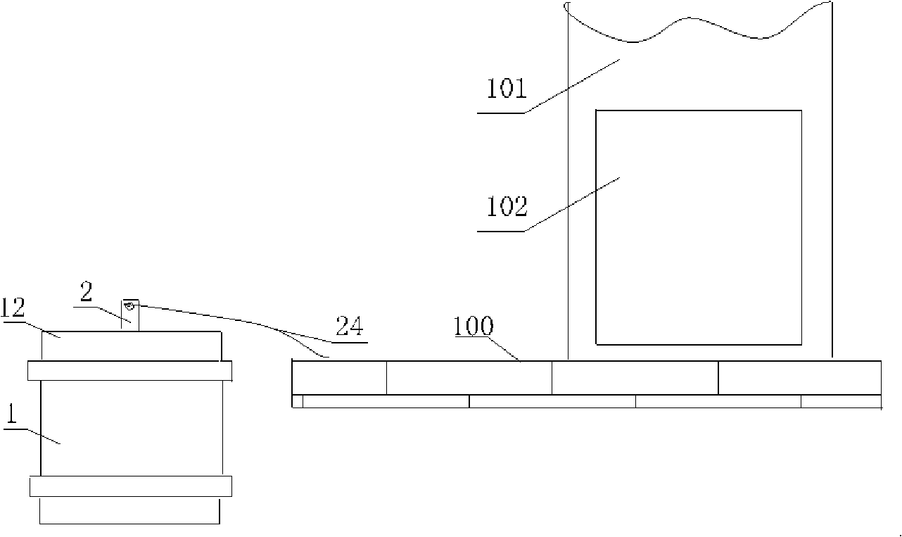
[0021] see figure 1 . The pneumatic pipeline transmission system includes an operation console 100, a transmission pipeline sending (receiving) device 101 and a conveyor. An inlet 102 (exit) is provided on the transmission pipeline sending and receiving device 101 . After the conveyer is filled with items to be transported, it enters the transmission pipeline sending (receiving) device 101 through the entrance 102, and the device is connected with the transmission pipeline, transported to a designated location, and then taken out by the exit. The transmitter therein comprises a bucket body 1 and a cover body 12 . The conveyor of the present invention is mainly used to prevent the bucket body 1 and the cover body 12 from being separated during the transmission process.

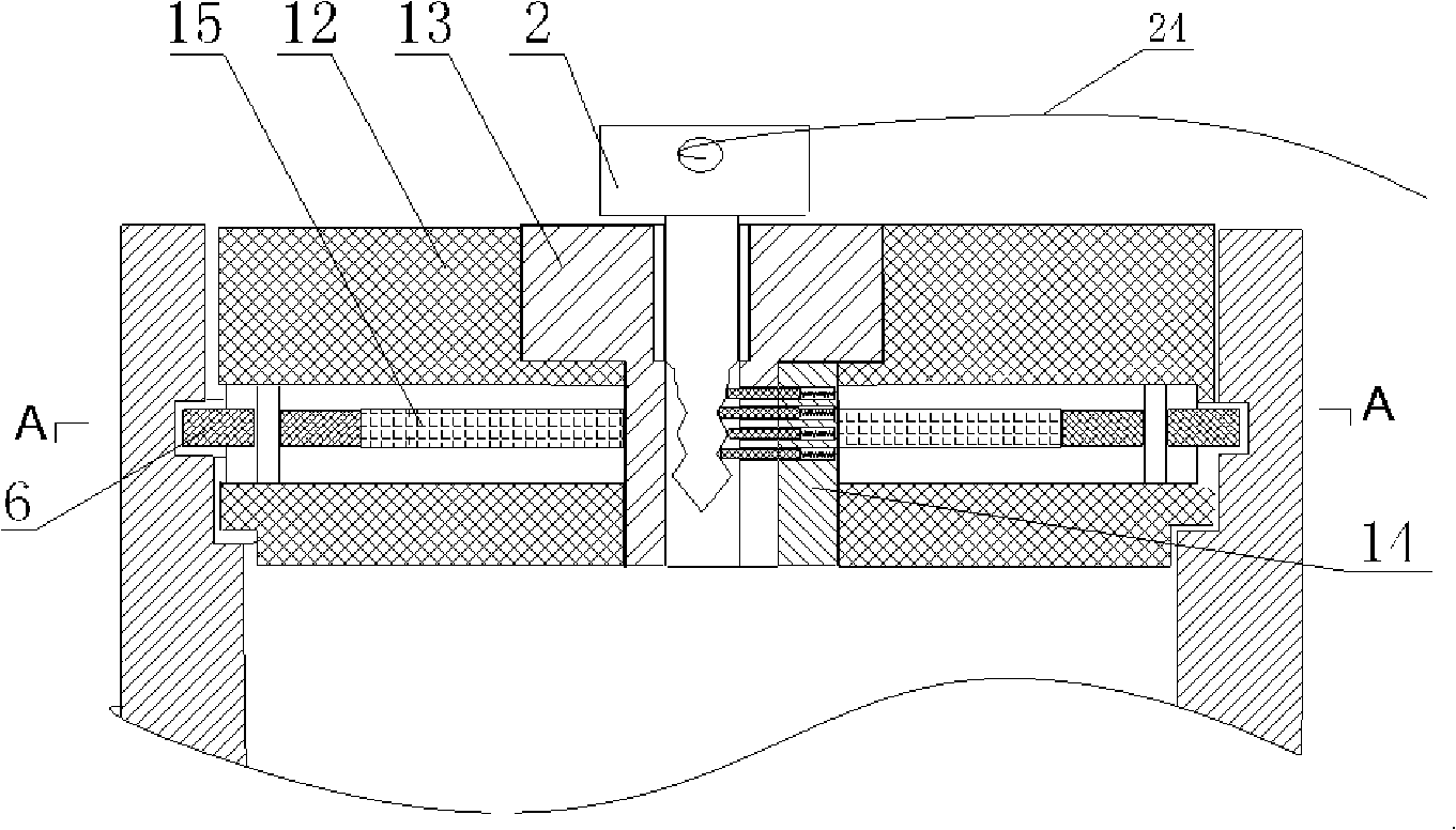
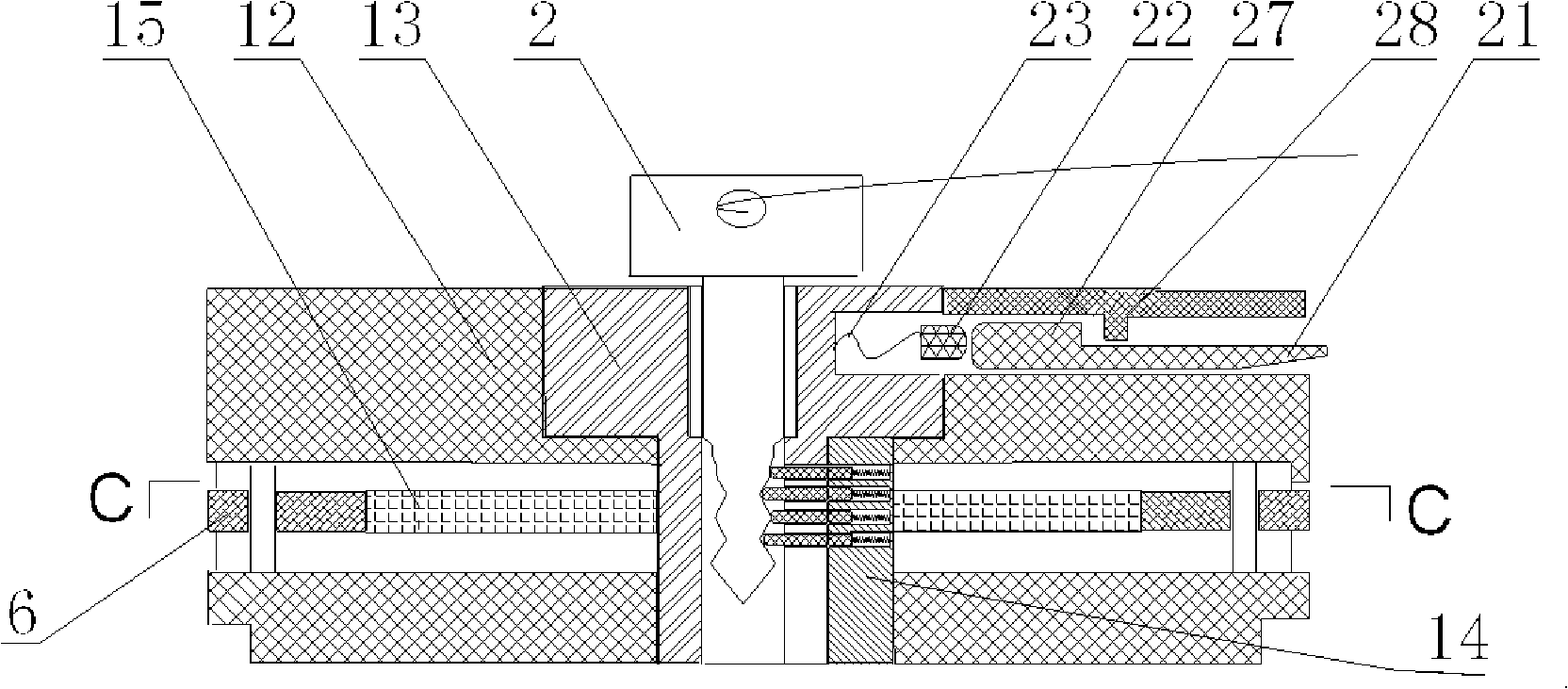
[0022] Such as figure 2 , image 3 , Figure 4 and Figure 5 As shown, the conveyor with the restraining rope of the present invention includes a locking mechanism arranged on the barrel or cover of the...


PUM


Abstract

The invention relates to the pneumatic pipeline transmission field. A transmission device with a constraint rope comprises a bucket body, a cover body, a locking mechanism and a locking detection mechanism. The locking mechanism comprises a lock cylinder arranged in the center of the cover body, a key inserted into the lock cylinder, a face plate fixed outside the lock cylinder, a plurality of lock tongues in rotary connection with the cover body, as well as a lock tongue limit pin fixed on the cover body; a lock groove matched with the lock tongue is arranged on the bucket body; the locking detection mechanism comprises a cylinder block between the lock cylinder and the cover body, as well as a plurality of cylinders which are arranged inside the cylinder block to control whether the key can be pulled out; the flexible constraint rope is attached to the key; the other end of the flexible constraint rope is fixed on an operation table. The transmission device not only ensures the locking function, but also can be interlocked, which improves the safety reliability of the locking connection of the cover body and the bucket body of the transmission device, is favorable for improving transmission efficiency, and increases privacy. When the transmission device is not locked, as the transmission device is pulled by the flexible constraint rope and cannot enter a transmission channel, thereby further avoiding failure occurrence.

Description

technical field [0001] The invention relates to the field of pneumatic pipeline transmission, in particular to a conveyor with restraining ropes which ensures that the conveyor cannot be opened. technical background [0002] Pneumatic pipeline conveying system can be used in all walks of life, such as hospitals, banks, factories, office buildings, shopping malls, restaurants and other places where items need to be conveyed. The pneumatic pipeline transmission system connects various departments, and items can be efficiently transmitted between any two transceiver stations, which can save people from running around, save a lot of time, and greatly improve work efficiency. However, the conveyor often causes the item to fall out of the conveyor because its cover is not locked, causing the conveyor to be stuck in the middle of the transmission pipeline, causing the transmission system to be unsmooth; in addition, in some places such as banks and office buildings In places where...

Claims


Application Information

Patent Timeline
Patent Type & Authority Applications(China)
IPC IPC(8): B65G51/04B65G51/36E05B41/00E05B19/22E05B65/52
Inventor 陆洪瑞
Owner BEIJING RINRONG TECH
Learn More