Antenna, antenna apparatus, and communication device

An antenna and antenna element technology, applied in the field of antenna devices and communication equipment, can solve the problems of reduced gain, exceeding the space limit, unable to obtain high gain, etc., and achieve the effect of good degree of freedom and high gain

Inactive Publication Date: 2008-12-03
HITACHI METALS LTD
View PDF3 Cites 4 Cited by
  • Summary
  • Abstract
  • Description
  • Claims
  • Application Information

AI Technical Summary

Problems solved by technology

That is, in order to improve performance, if the dielectric or magnetic part is enlarged, it will be effective in improving the uniform gain performance, but it exceeds the space limit in a limited space
In addition, only in the case of a chip antenna composed of dielectric ceramics or magnetic ceramics and a conductor provided inside, there is also a problem that the gain reduction on the ultra-low frequency side of the frequency band used in portable communication equipment is large
[0007] And, if an antenna element combining the above-mentioned dielectric ceramics or magnetic body ceramics and the above-mentioned conductor is used, although a high gain is achieved in a specific frequency range in the frequency band, the lower frequency to higher frequency band range used in portable communication equipment Uniformly high gain cannot be obtained, especially in the higher frequency band, there is a problem that it is not suitable for applications such as quad-band portable communication devices with low VSWR and high gain in the ultra-wide frequency band.

Method used


Image

  • Antenna, antenna apparatus, and communication device
  • Antenna, antenna apparatus, and communication device
  • Antenna, antenna apparatus, and communication device

Examples


Embodiment Construction

[0052] Hereinafter, specific embodiments of the present invention will be described. In addition, the same code|symbol is attached|subjected to the same component.

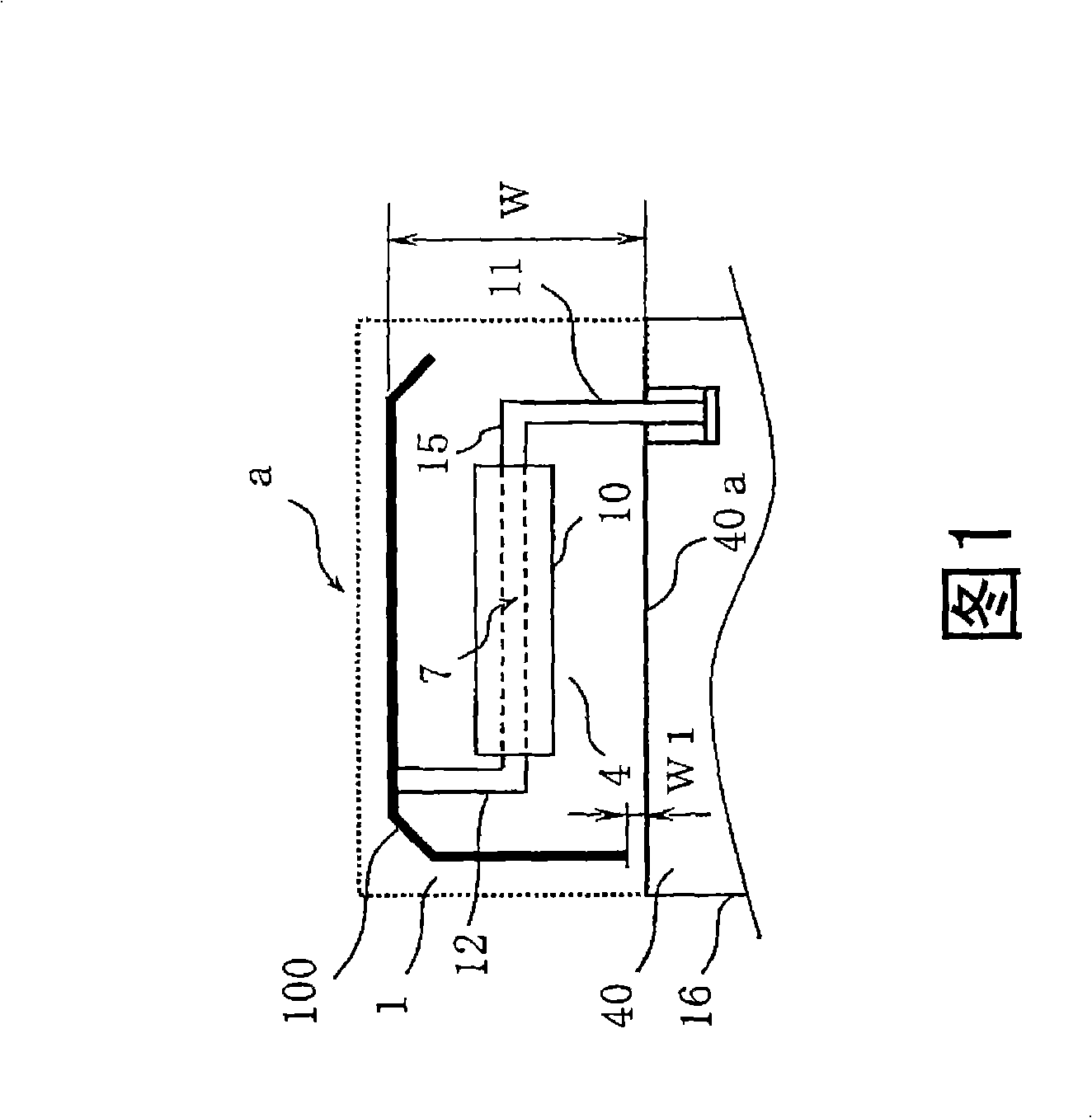
[0053] FIG. 1 shows one form of an antenna according to an embodiment of the present invention. Antenna a in FIG. 1 is an antenna having a substrate (a magnetic chip or a dielectric chip) and a conductor. The antenna can be mounted on a substrate for use. FIG. 1 is a plan view of the antenna of this embodiment (corresponding to a view viewed from above the substrate surface when the antenna is mounted on the substrate).

[0054] As shown in FIG. 1 , the antenna of this embodiment includes: a first substrate 10; a first antenna element 4 having a conductor 7 disposed inside the substrate; and a second antenna element 1 having a plate-shaped conductor portion 100 and a connecting conductor. 12. And, the connection conductor 12 is connected in the middle of the plate-shaped conductor part 100 . If the conductor ...


PUM


Abstract

An antenna is provided which includes a first antenna element having at least one base and a conductor penetrating through the base and a second antenna element having a conductor portion having a shape of a plate or a line and a connecting conductor, wherein a first end of the conductor of the first antenna element is connected to the connecting conductor of the second antenna element, and the connecting conductor of the second antenna element is connected to a partway on the conductor portion of the second antenna element.

Description

technical field [0001] The present invention relates to an electronic device having a communication function, and more particularly to an antenna used in a communication device such as a mobile phone and a portable terminal device, and an antenna device and a communication device using the antenna. Background technique [0002] The frequency band used by communication devices such as mobile phones and wireless LANs is several hundred MHz to several GHz, and high gain and high efficiency are required in this frequency band. Therefore, on the premise that the antenna used therein operates with a high gain in this frequency band, its use state is required to be particularly small and flat. In addition, in recent years, it has been proposed to use one mobile phone to cope with four frequency bands (quad band) among the GSM frequency band (810-960MHz), DCS / PCS and UMTS frequency band (1710-2170MHz). wide frequency band. [0003] Conventionally, as a small antenna suitable for m...

Claims


Application Information

Patent Timeline
Patent Type & Authority Applications(China)
IPC IPC(8): H01Q1/36H01Q1/38H01Q9/04H01Q21/30H01Q1/24
Inventor 青山博志权田正幸
Owner HITACHI METALS LTD
Why Eureka
Try Eureka