Terminal material strip structure and method for removing material strip of terminal material strip

A strip and terminal technology, which is applied in the field of terminal strip structure and strip removal, can solve the problems of increased production man-hours and difficulty in folding materials, and achieve the effect of reducing difficulty

Active Publication Date: 2008-12-03
DEYI PRECISION ELECTRONIC IND CO LTD PANYU
View PDF0 Cites 8 Cited by
  • Summary
  • Abstract
  • Description
  • Claims
  • Application Information

AI Technical Summary

Problems solved by technology

[0002] Please refer to Fig. 18, which is a front view of an existing strip connected to a conductive terminal. The strip 6 is provided with a plate portion 60 on which A plurality of positioning holes 61 are provided for positioning and feeding. The lower end of the plate portion 60 is provided with a plurality of extension portions 62 on the same plane as the plate portion 60. The conductive terminal 7 is provided with a strip connecting portion 70. The strip The connection part 70 is connected to the extension part 62, and a pre-break line 620 is provided between the two, and th

Method used


Image

  • Terminal material strip structure and method for removing material strip of terminal material strip
  • Terminal material strip structure and method for removing material strip of terminal material strip
  • Terminal material strip structure and method for removing material strip of terminal material strip

Examples


Example Embodiment

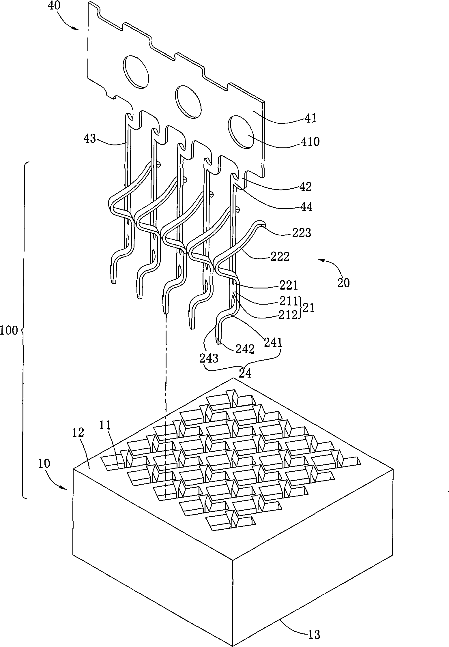
[0022] The present invention will be further described below with reference to the accompanying drawings and specific embodiments.

[0023] Please refer to figure 1 and Figure 5 , the present invention relates to an electrical connector 100, which is used to electrically connect a chip module (not shown) to a circuit board (not shown), which includes: an insulating body 10, multiple rows of terminals 20 and terminals 20 corresponds to 30 solder balls (such as Figure 5 ), wherein the insulating body 10 is provided with multiple rows of terminal accommodating grooves 11, and the terminals 20 are correspondingly accommodated therein; the solder balls 30 are installed in the terminal accommodating grooves 11 and abut with the corresponding terminals 20 (eg, Figure 5 ).

[0024] Please refer to figure 1 , Figure 5 and Image 6 , the insulating body 10 is roughly in the shape of a rectangular parallelepiped, which has a first surface 12 and a second surface 13 opposite to ...


PUM


Abstract

The invention provides a terminal material band structure, comprising at least a material band and a plurality of conductive terminals which are connected on each material band; each material band is provided with a plate part; one end of the plate part is provided with a plurality of extension parts which use a common surface with the plate part; the end of each extension part is bent and extended to form a connecting plate; the end of the connecting plate is connected with a conductive terminal; each terminal is provided with a material band connecting part which is connected with the connecting plate; the material band connecting part is arranged on the extension surface of the connecting plate; furthermore, the connection position of the material band connecting part and the connecting plate is provided with a pre-cutting line; the pre-cutting line and the extension surface of the plate part form an angle. Compared with the prior art, the terminal material band structure of the invention leads the pre-cutting line and the extension surface of the plate part to form an angle, therefore, when the material band is broken, the material band applies an oblique pulling force on the conductive terminal so as to lead one end of the pre-cutting line to generate a tearing gap, lead the longitudinal connecting plate and the material band connecting part to be separated at the pre-cutting line position, and reduce the breaking difficulty of the material band.

Description

【Technical field】 [0001] The present invention relates to a terminal strip structure and a strip removal method of the terminal strip. 【Background technique】 [0002] Please refer to FIG. 18 , which is a front view of a conventional connection between a material tape and a conductive terminal. The material tape 6 is provided with a plate portion 60 , and the plate portion 60 is provided with a plurality of positioning holes 61 for positioning and feeding. The lower end of the part 60 is provided with a plurality of extension parts 62 which are located on the same plane as the plate part 60 , and a strip connecting part 70 is provided on the conductive terminal 7 , and the strip connecting part 70 is connected with the extending part 62 , and a strip connecting part 70 is arranged therebetween. There is a pre-break line 620, and the pre-break line 620, the strip connecting part 70, the extension part 62 and the plate part 60 are located on the same plane, so when the strip 6 ...

Claims


Application Information

Patent Timeline
IPC IPC(8): H01R43/16
Inventor 朱德祥
Owner DEYI PRECISION ELECTRONIC IND CO LTD PANYU
Why Eureka
Try Eureka