High-capacity direct current de-icing device

A DC ice melting, large-capacity technology, applied in the output power conversion device, AC power input is converted into DC power output, irreversible AC power input is converted into DC power output, etc. problems such as poor production, real-time and rapidity, to meet the needs of ice melting and facilitate transportation and movement

Inactive Publication Date: 2008-12-03
STATE GRID ELECTRIC POWER RES INST
View PDF0 Cites 37 Cited by
  • Summary
  • Abstract
  • Description
  • Claims
  • Application Information

AI Technical Summary

Problems solved by technology

The problem with this method is that it is necessary to connect special ice-melting equipment for the corresponding lines, and temporarily change the wiring of the generator excitation system. The pre-ice-melting preparation workload is large, the real-time performance and rapidity are poor, and it is only suitable for medium and short distances. line melting ice
[0011] (1) To implement three-phase short-circuit ice melting, it is necessary to stop the overhead transmission line in all ice melting circuits including the ice melting line. The ice melting power is usually provided by the system, so the impact closing method can only be adopted. Low and insufficient reactive power reserve may disrupt system stability
[0012] (2) The preparation work in the early stage of ice melting is very heavy, which requires the cooperation of multiple departments such as dispatching, operation, and relay protection, which affects normal production;
[0013] (3) Three-phase short-circuit ice melting consumes a lot of power, and the electricity required for one ice melting is usually tens of thousands of kWh or more.
[0014] (4) This method is only feasible for lines with a voltage level of 220kV and below. Since the ice-melting power supply is difficult to solve, it is basically impossible to implement for lines of 500kV and above, that is, using a lower voltage level as the ice-melting power supply, and the ice-melting line is too short; The use of high voltage levels requires the system to provide huge reactive power
[0028] Even if thyristors (5-inch silicon wafers) are used in direct current transmission projects (HVDC), their rated current is 3kA, so the current capacity of 500kV direct current transmission projects is limited to within 3000MW; while UHV HVDC projects will use 6-inch silicon wafers, Its rated current can only reach 4 ~ 4.5kA, which cannot meet the current requirements of the DC ice melting device.

Method used


Image

  • High-capacity direct current de-icing device
  • High-capacity direct current de-icing device
  • High-capacity direct current de-icing device

Examples


Embodiment approach

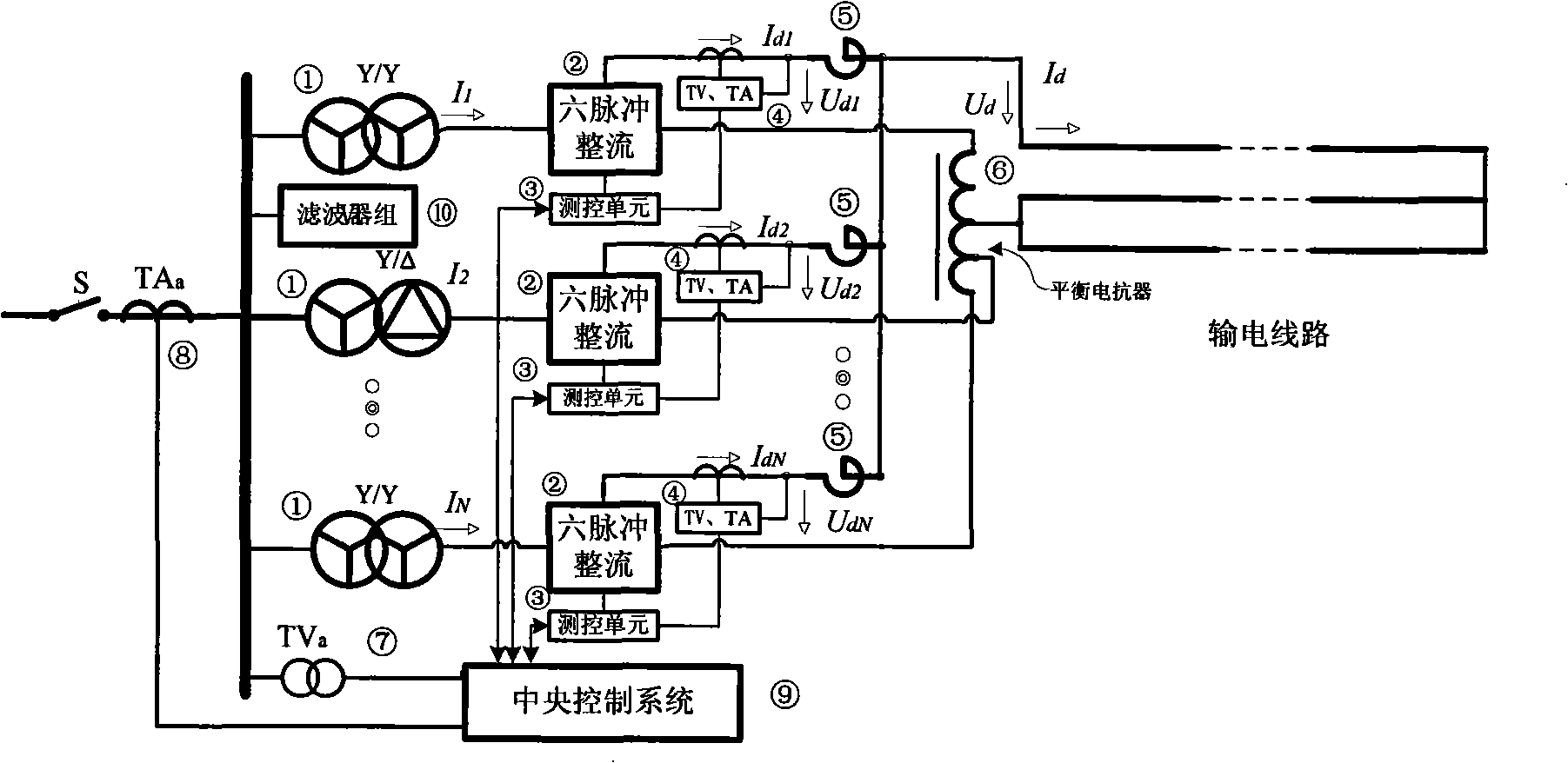
[0048] see image 3 . The embodiment of the present invention is: a large-capacity DC ice-melting device, which is characterized in that it includes a rectifier transformer ①, a six-pulse rectifier ②, a measurement and control unit ③, a DC voltage, a current transformer TV, TA ④, a DC smoothing reactor ⑤, Balance reactor ⑥, AC voltage transformer TV a ⑦, AC current transformer TA a ⑧ and central control system ⑨;

[0049] It has N six-pulse rectifiers ② with the same parameters, N is greater than or equal to 2, and N measurement and control units ③ provide trigger pulses for each six-pulse rectifier ② independently, and simultaneously collect the signals of DC voltage and current transformer TV, TA ④ for analysis and calculation The output voltage and current value of the six-pulse rectifier ②; the input end of the DC ice-melting device is equipped with an AC voltage transformer TV a ⑦, AC current transformer TA a ⑧, its output is connected to the central control system, ...


PUM


Abstract

The invention provides a large-capacity DC thawing apparatus, comprising a rectifier transformer, six-pulse rectifier, measurement and control units, a DC voltage and current transformer TV and TA, a DC smoothing reactor, a balancing reactor, an AC voltage transformer TVa, an AC current transformer TAa and a central control system; the large-capacity DC thawing apparatus has N six-pulse rectifiers with identical parameters; N measurement and control units respectively provide triggering pulses for each six-pulse rectifier; the input terminal of the DC thawing apparatus is provided with the AC voltage transformer TVa and AC current transformer TAa and the output terminal thereof is connected with the central control system; the output anodes of the N six-pulse rectifiers are directly connected in parallel by the smoothing reactor and connected with one end of the transmission line to be thawed and the output cathode thereof is connected with the other end of the transmission line to be thawed in parallel by N tap balance reactors. By adopting the parallel running technique of the rectifier, the problems of the large-capacity DC thawing apparatus such as large current, high voltage and large capacity are solved.

Description

technical field [0001] It belongs to ice-melting equipment for power transmission lines. Background technique [0002] The icing of transmission lines in winter is one of the major natural disasters in the power system. The consequences of accidents such as interruption of power supply or even disconnection of the power grid caused by icing are usually extremely serious, and the repair work is difficult and takes a long time. In order to solve this difficult problem that seriously threatens the safe operation of the power system, countries all over the world have invested a lot of manpower and material resources in research. At present, the deicing methods of transmission lines mainly include thermal deicing, mechanical deicing, and passive deicing. Because most of the high-voltage transmission lines are erected in the wilderness and among the mountains, once ice is formed, it is difficult to achieve the purpose of timely deicing by mechanical deicing in terms of the curre...

Claims


Application Information

Patent Timeline
Patent Type & Authority Applications(China)
IPC IPC(8): H02G7/16H02M7/12H02M7/162H02M1/12
Inventor 李澍森吴夕科陈晓燕石延辉左文霞程军照李敏桂朋林
Owner STATE GRID ELECTRIC POWER RES INST
Why Eureka
Try Eureka