Direct current transmission system with grounding polar circuit melting function and operation method therefor

A technology of direct current transmission system and power transmission system, which is applied in the installation of electrical components, cables, overhead installation, etc., which can solve the problems of unable to meet the needs of ice melting and short running time, and achieve the effect of simple structure and satisfying ice melting

Pending Publication Date: 2018-10-16
ELECTRIC POWER RESEARCH INSTITUTE, CHINA SOUTHERN POWER GRID CO LTD
View PDF0 Cites 2 Cited by
  • Summary
  • Abstract
  • Description
  • Claims
  • Application Information

AI Technical Summary

Problems solved by technology

Although theoretically it is possible to use the single-pole ground loop operation mode to melt ice on the ground electrode line, but due to various factors, the single-pole ground loop operation mode of the HVDC transmission system in the actual project allows a very short running time, which cannot meet the requirements for melting ice. ice needed

Method used


Image

  • Direct current transmission system with grounding polar circuit melting function and operation method therefor
  • Direct current transmission system with grounding polar circuit melting function and operation method therefor
  • Direct current transmission system with grounding polar circuit melting function and operation method therefor

Examples


Embodiment Construction

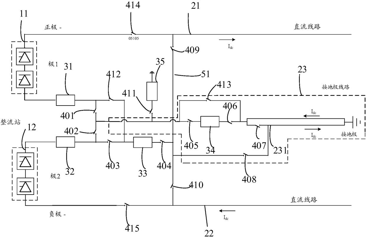
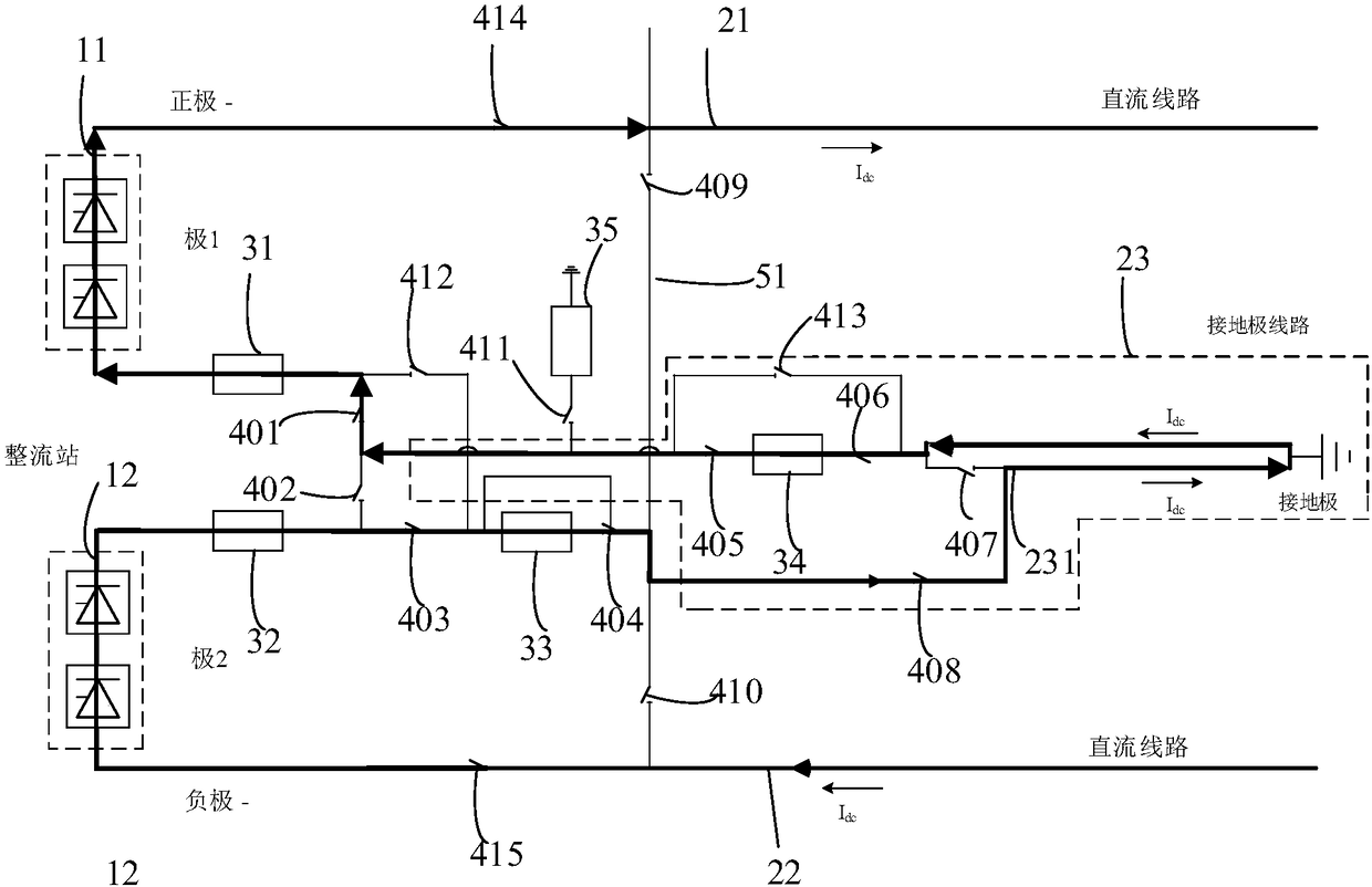
[0024] Such as figure 1 As shown, a direct current transmission system with the function of melting ice on ground pole lines includes a first pole switching valve group 11 , a second pole switching valve group 12 , a first pole transmission line 21 and a second pole transmission line 22 . In a specific embodiment, the first pole power transmission line 21 is a positive pole power transmission line, and the second pole power transmission line 22 is a negative pole power transmission line.

[0025] The first end of the first pole switching valve group 11 is connected to one end of the first pole transmission line 21; the first end of the second pole switching valve group 12 is connected to one end of the second pole transmission line 22; the first pole switching valve The second end of the group 11 is connected to the ground electrode line 23 through the first circuit breaker 31 and the first knife switch 401; the second end of the second pole commutation valve group 12 is conne...


PUM


Abstract

The invention relates to a direct current transmission system with a grounding polar circuit melting function. The bipolar high voltage direct current transmission system passes through a seventh breaker which is added to one of the two phase conductors of the grounding polar circuit and an eighth breaker which are connected to the seventh breaker. By cutting off the seventh breaker, closing the eighth breaker, and cutting off the second breaker, closing the third breaker, the fourth breaker and the third circuit breaker can connect the other one of the two phase conductors to a first polar converter valve group and a first polar transmission circuit, so that the part segment of one of two phase conductors provided with the seventh breaker is connected to a second polar converter valve group and a second polar transmission circuit, and connected to the other one of the two phase conductors, so that after starting the high voltage direct current transmission system, a direct current flows through the two phase conductors of the grounding polar circuit, and the direct current is more than the minimum melting current of the single phase in the two phase conductors of the grounding polar circuit, and is smaller than the maximum allowable current of the single phase in the two phase conductors of the grounding polar circuit, and continuously running until the ice on the grounding polar circuit is completely melted. The system is simple in structure and can meet the requirement of rounding polar circuit melting.

Description

technical field [0001] The invention relates to the field of high-voltage direct current power transmission, in particular to a direct current power transmission system with the function of melting the ice of a ground electrode line and an operating method thereof. Background technique [0002] Among the various natural disasters suffered by the power system, ice disaster is one of the most serious threats. In recent years, various meteorological disasters around the world have become more frequent, extreme weather and climate events have become more abnormal, and ice disasters have caused more serious losses and impacts on the power system, making it more and more difficult for the power system to respond to ice disasters. [0003] HVDC (High Voltage Direct Current Transmission) has the advantages of large transmission capacity and low loss, flexible and reliable power regulation, no stability problem of synchronous operation, and asynchronous networking between power syste...

Claims


Application Information

Patent Timeline
Patent Type & Authority Applications(China)
IPC IPC(8): H02G7/16
CPCH02G7/16
Inventor 傅闯饶宏许树楷邹家勇吴怡敏余波
Owner ELECTRIC POWER RESEARCH INSTITUTE, CHINA SOUTHERN POWER GRID CO LTD
Why Eureka
Try Eureka