Electric inverter

A power conversion device and power conversion technology, which are applied in the direction of converting irreversible AC power input to DC power output, and converting irreversible DC power input to AC power output.

Inactive Publication Date: 2008-12-03
HITACHI LTD
View PDF1 Cites 8 Cited by
  • Summary
  • Abstract
  • Description
  • Claims
  • Application Information

AI Technical Summary

Problems solved by technology

[0007] The problem to be solved by the present invention is to suppress the phenomenon of uneven current generated when the capacitors in the power

Method used


Image

  • Electric inverter
  • Electric inverter
  • Electric inverter

Examples


Embodiment Construction

[0031] Embodiments of the present invention will be described below with reference to the drawings.

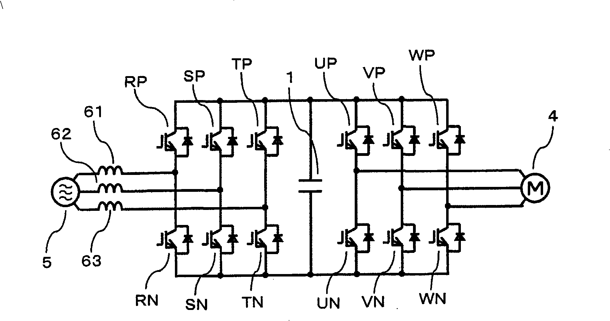
[0032] first image 3 The main circuit configuration of the power conversion device to which the present invention is applied is shown. Such as image 3 As shown, any AC current from the 3-phase AC power supply 5 passes through the forward conversion circuit (converter (converter circuit) and an inverse conversion circuit (inverter circuit) for converting DC power to AC power consisting of smoothing capacitor 1 and IGBT·UP to WN are supplied to motor 4 . and, image 3 Each of the switching elements and smoothing capacitors in the power conversion device is composed of a plurality of parallel or series-parallel connections according to the power capacity of the power conversion device.

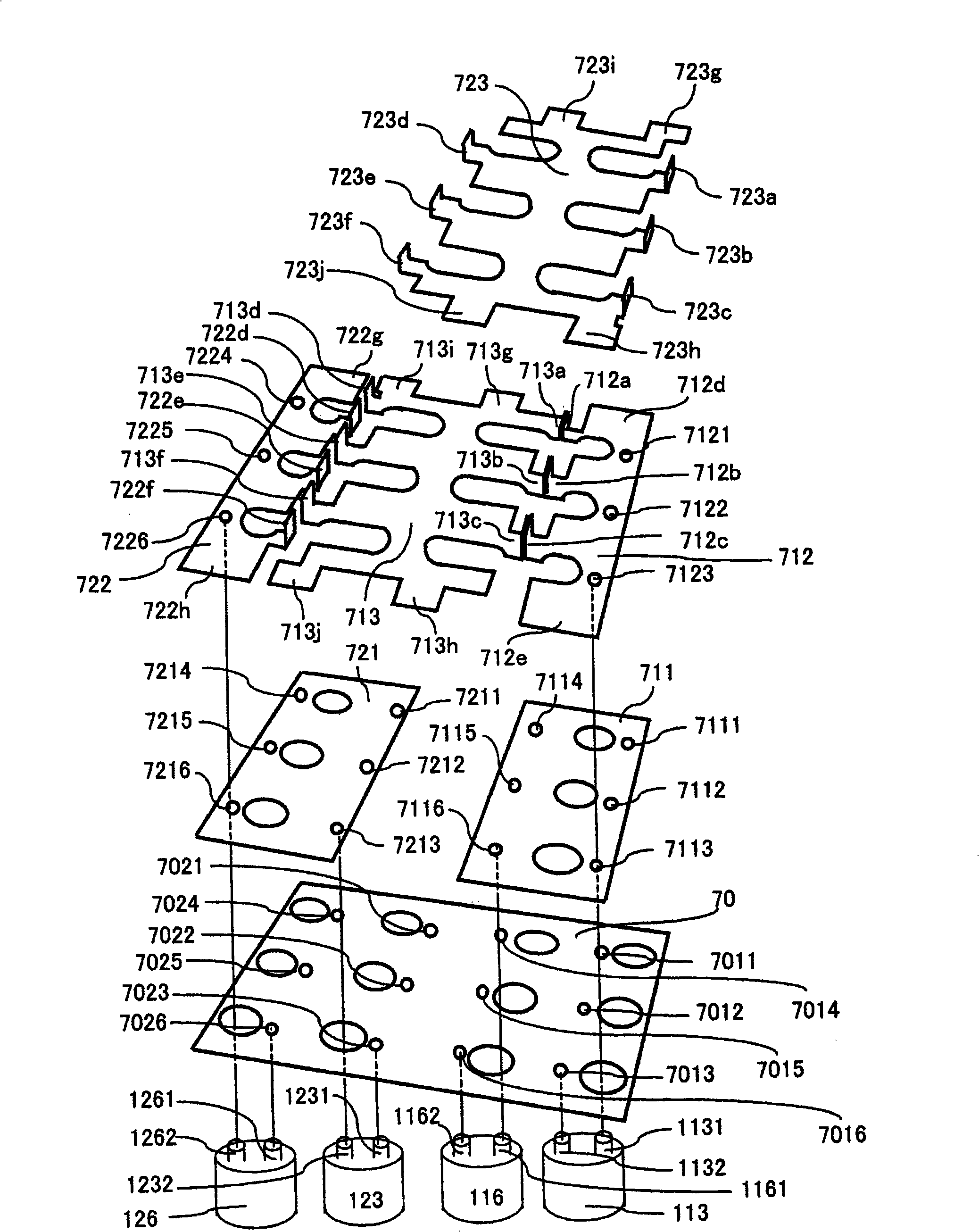
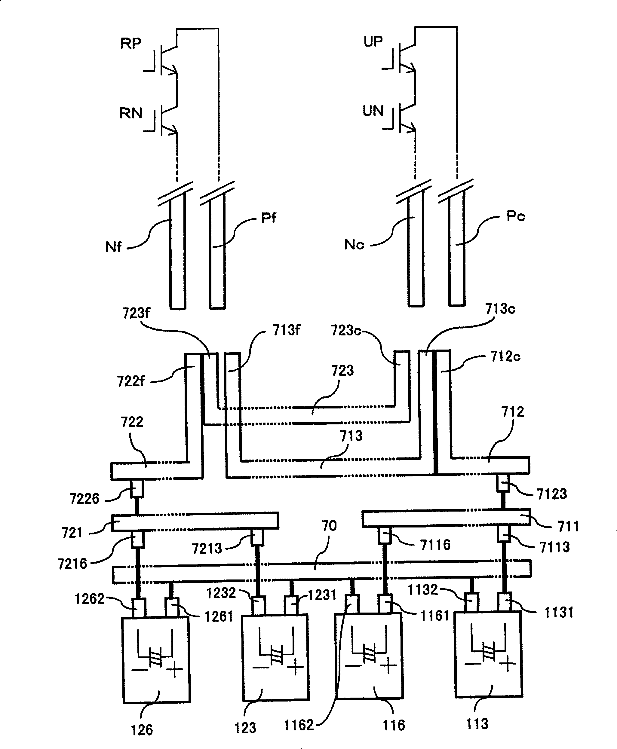
[0033] Figure 4 A configuration of one phase including one phase of a forward conversion circuit, one phase of an inverse conversion circuit, and a part of a smoothing capacitor connected...


PUM


Abstract

The invention is to implement large capacity of a power conversion device without increasing size of the device. The provided power conversion device comprises: a first conductor electrode with a plate-shaped part and a vertical part, the plate-shaped part is connected with anode terminal or cathode terminal of a capacitor and roughly parallel mounted with planes setting each terminal so as to cover the capacitor group, the vertical part is connected with direct current side of the first power conversion circuit and vertical to the planes; and a second conductor electrode with a similar plate-shaped part, a part which is connected with vertical part of the first conductor electrode and vertical to the planes and a part which is connected with direct current side of the second power conversion circuit and vertical to the planes. Thus, degree of non-homogeneous of current running through each capacitor may be alleviated such that large capacity may be implemented without increasing size of the power conversion device.

Description

technical field [0001] The present invention relates to a power conversion device including a circuit in which a plurality of capacitors are connected in parallel. Background technique [0002] Power conversion devices using high-speed semiconductor switching elements such as insulated gate bipolar transistors (IGBTs) are widely used in various fields. In recent years, with the advancement of semiconductor technology, large-capacity semiconductor modules have been developed, and a plurality of semiconductor modules are further connected in parallel to achieve greater capacity. [0003] In a power conversion device, when semiconductor modules are connected in parallel to increase the capacity, the charge and discharge current in the smoothing capacitor constituting the DC power supply of the inverter increases. Therefore, it is often necessary to connect a plurality of capacitors in parallel. Different voltages are also connected in series. When capacitors are connected in ...

Claims


Application Information

Patent Timeline
IPC IPC(8): H02M7/48H02M7/12
Inventor 森和久伊君高志岸川孝生迫田友治大沼直人蛭田清玄
Owner HITACHI LTD
Why Eureka
Try Eureka