
Forcedly stretching hole structure and stretching rolling method for rolling strip steel

A pass and strip technology, applied in the direction of metal rolling, metal rolling, rolls, etc., can solve the problem of small expansion, and achieve the effect of increasing the expansion, widening the product, and improving the efficiency of the rolling mill.

Inactive Publication Date: 2008-12-10
NORTH CHINA UNIVERSITY OF SCIENCE AND TECHNOLOGY
View PDF0 Cites 15 Cited by
  • Summary
  • Abstract
  • Description
  • Claims
  • Application Information

AI Technical Summary

Problems solved by technology

However, according to the current rolling with split wedge pass, the amount of expansion is small, generally 20-30mm, and the maximum can reach 40-100mm

Method used


Image

  • Forcedly stretching hole structure and stretching rolling method for rolling strip steel
  • Forcedly stretching hole structure and stretching rolling method for rolling strip steel
  • Forcedly stretching hole structure and stretching rolling method for rolling strip steel

Examples


Embodiment 1

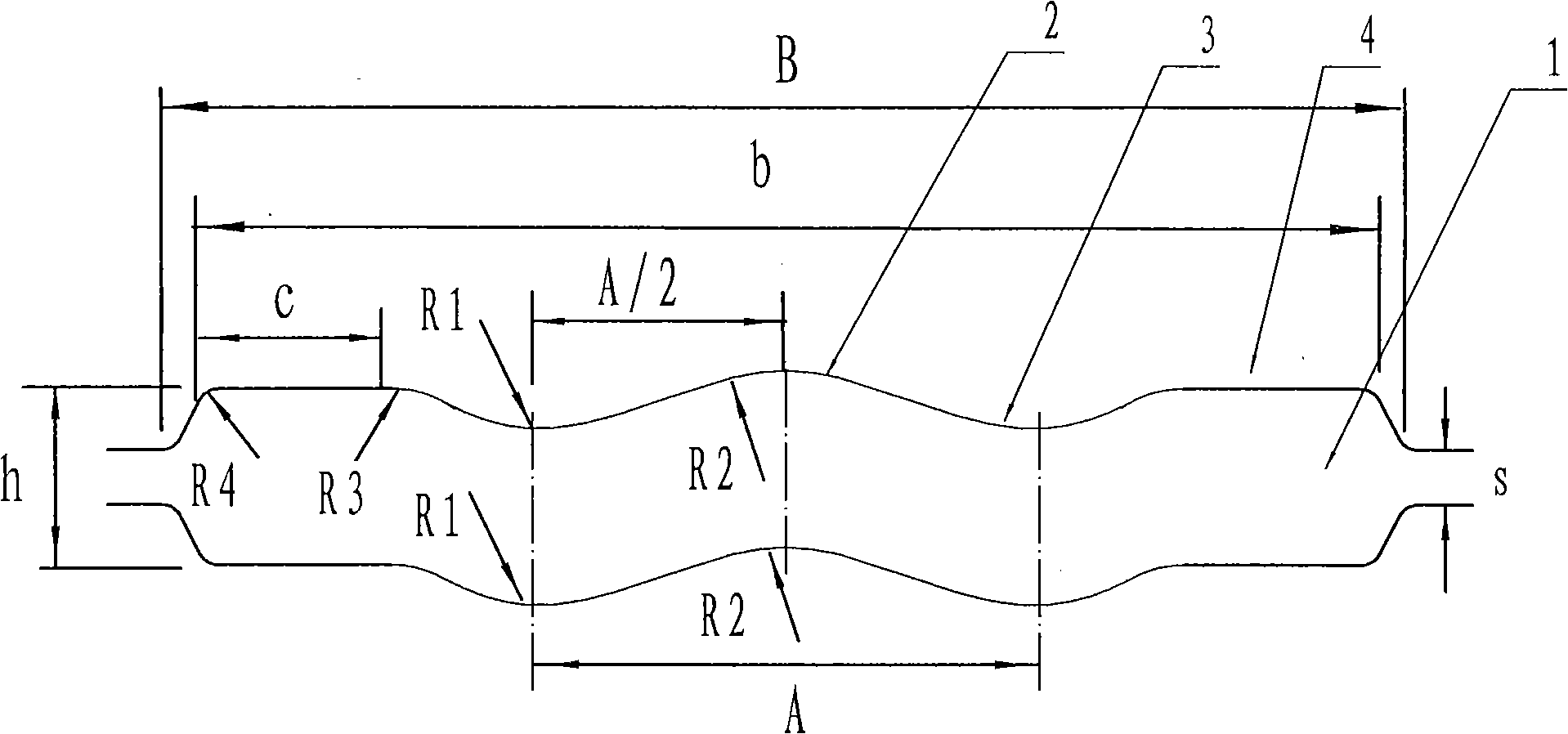
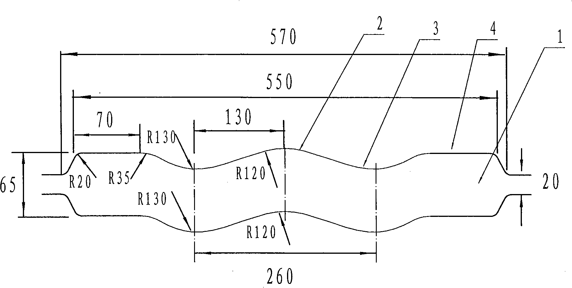
[0019] Embodiment 1: the slot width of the pass is B=570mm, the width of the groove bottom of the pass is b=550mm, the wave-shaped bending center distance A=0.456B=260mm, R1=0.228B=130mm, R2=0.21B=120mm , C=0.123B=70mm. Roll gap S=20mm, pass height h=65, arc R3=35mm, R4=20mm.

Embodiment 2

[0020] Embodiment 2: the slot width of the pass is B=570mm, the groove bottom width of the pass is b=550mm, the wave-shaped bending center distance A=0.44B=251mm, R1=0.22B=125mm, R2=0.20B=114mm , C=0.12B=68mm. The roll gap S=20mm, the height of the pass h=65mm, the arc R3=35mm, R4=20mm.

Embodiment 3

[0021] Embodiment 3: the slot width of the pass is B=570mm, the groove bottom width of the pass is b=550mm, the wave-shaped bending center distance A=0.47B=270mm, R1=0.24B=137mm, R2=0.22B=125mm , C=0.13B=74mm. The roll gap S=20mm, the height of the pass h=65mm, the arc R3=35mm, R4=20mm.

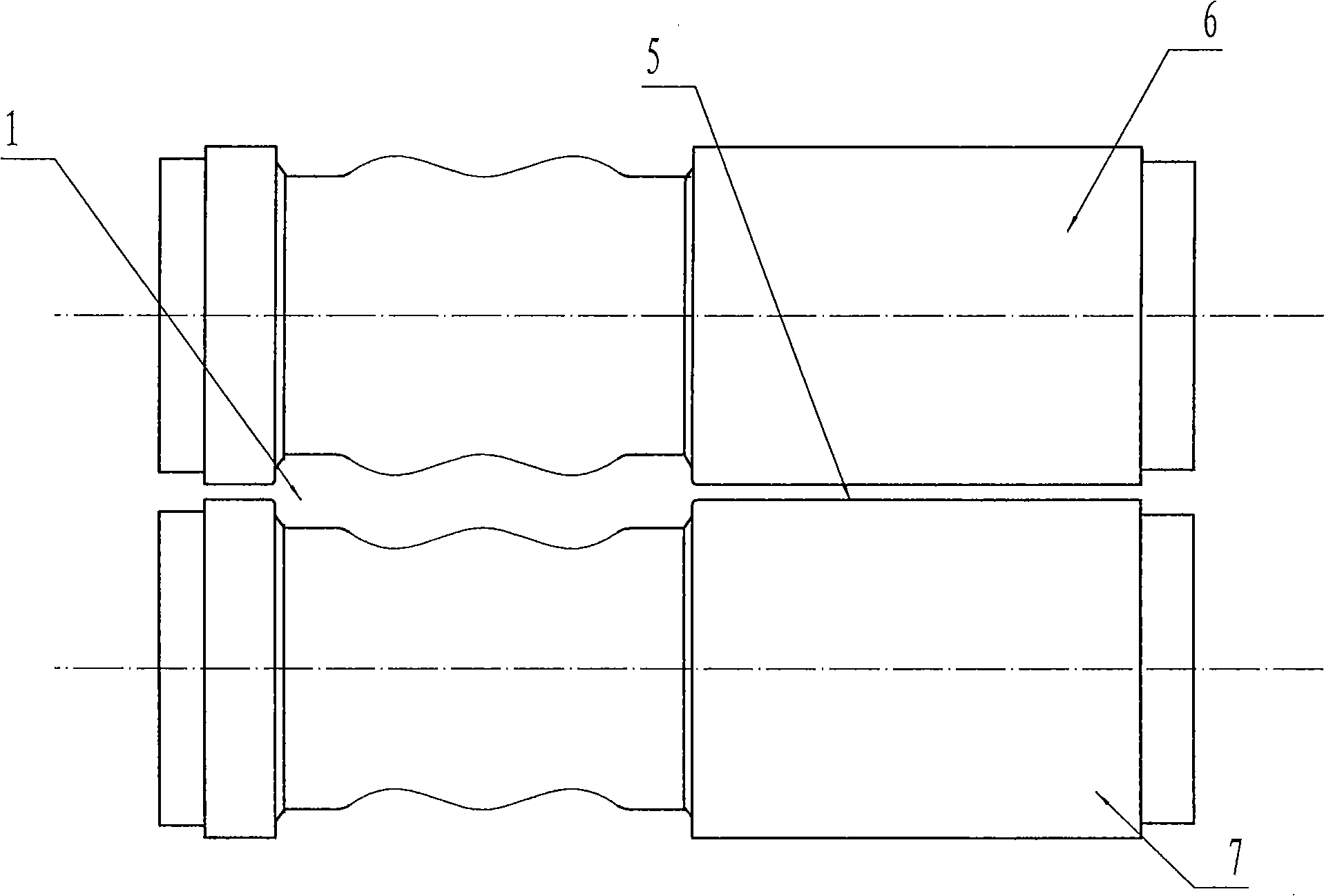
[0022] The widening and rolling method of the present invention is carried out on a roughing mill. The steel billet with a rectangular boundary section is first rolled on the above-mentioned wave-shaped forced widening pass to roll out a rolled piece with a wave bend, and then passes through a flat rolling pass or a flat roll. Rolling, in which, the first pass of flat rolling pass or flat roll rolling is flattening rolling. Flattening rolling will flatten and flatten the rolled piece with wavy bends. There is no reduction in the thickness direction of the rolled piece, but it needs Flattening and pressing, the amount of the flattening and pressing is the amplitude height of the wavy bend of ...


PUM

PropertyMeasurementUnit
lengthaaaaaaaaaa

Abstract

The invention discloses a force broadening pass structure used for strip rolling and a broadening rolling method thereof, and belongs to the technical field of steel rolling; the invention is used for solving the problem of increasing the broadening degree of the strip rolling. After improvement, the pass is composed of a wave curve outline part and a linear outline part of an upper roll and a lower roll, the wave curve camber of the upper and the lower rolls are uniformly corresponding to each other, and the linear outline part is positioned at the two ends of the wave curve. The broadening rolling method of the invention includes that a rolled piece is firstly broadened and rolled on the force broadening pass, then goes through flat rolling pass or flat roll rolling, the first pass of the flat rolling pass or the flat roll rolling is broadening rolling, and broadening rolling reduction is matched with the wave bending amplitude of the rolled piece in the first pass. By adopting the force broadening pass structure of the invention, the broadening degree can reach 100-150mm, thus achieving the aim of significantly increasing the broadening, degree and realizing that a wider strip steel can be rolled by a relatively narrow continuous casting slab. The force broadening pass structure of the invention is beneficial for widening products, increasing the efficiency of a mill, and leading strip production to be more flexible.

Description

technical field [0001] The invention relates to a roll pass and a rolling method, in particular to a forced widening pass structure for strip steel rolling and a rolling method using the pass, belonging to the technical field of steel rolling. Background technique [0002] Forced widening pass is a strip rolling technique that uses narrower billets to roll wider strips. In the production of narrow strips and medium and wide strips, the types of steel billets generally used are limited in width. How to roll wider strips requires the use of forced widening passes in rough rolling. At present, the forced widening pass is used in both narrow strip and medium wide steel production plants, for example: a single split wedge forced widening pass with a raised split wedge in the middle of the pass, during the rolling process Under the action of the split wedge, the material can flow to both sides, thereby increasing the amount of slab widening. This technology can use narrower bille...

Claims


Application Information

Patent Timeline
Patent Type & Authority Applications(China)
IPC IPC(8): B21B1/22B21B27/02
Inventor 刘战英刘阳周满春马劲红郭转林王学慧陈瑾
Owner NORTH CHINA UNIVERSITY OF SCIENCE AND TECHNOLOGY
Learn More