Clamping apparatus for cloth roller

A cloth roll and plane technology, which is applied in the field of clamping devices, can solve the problems of the square-end connecting shaft 4 with complex shape, bad stress state, and high machining cost, and achieve good stress state, simple shape, and easy maintenance Effect

Inactive Publication Date: 2008-12-10
杨希霞
View PDF0 Cites 12 Cited by
  • Summary
  • Abstract
  • Description
  • Claims
  • Application Information

AI Technical Summary

Problems solved by technology

[0003] This clamping device is fast and safe when changing the cloth roll, but it also has serious defects: first, as figure 1 , figure 2 As shown, there is a gap δ between the upper plane 51 of the square hole of the chuck 5 and the upper plane 41 of the square groove of the square end connecting shaft 4, and the gap δ is generally about 2mm. Due to the existence of the gap δ, the roll Every time the cloth roller rotates once, its square shaft head will move up and down in the square groove of the square end connecting shaft 4, which not only produces noise, but also produces impact force, which makes the bearing easy to damage; roll from figure 2 After the position shown is rotated by 180 degrees, the weight of the entire cloth roll and the cloth rolling roller falls on the long pin 6. In addition to the influence of the above-mentioned impact force, the stress state of the long pin 6 is very bad at this time. When the long pin 6. After a certain number of cyclic shear stresses, the whole device will fail after the deformation reaches a certain level and must be repaired. However, since the long pin has been deformed, it is difficult to take it out from the pin hole, which brings great trouble to the maintenance. Difficult; the 3rd, the shape of square-end connecting shaft 4 is more complicated, and machining cost is high; When processing on common lathe, the positional tolerance between the pin hole on the chuck 5 and the square hole is more difficult to control, the axis of pin hole If the distance from the upper plane 51 of the square hole is too small, the chuck 5 will interfere with the square end connecting shaft 4 when rotating around the long pin 6, and if the distance is too large, the gap δ will increase, further increasing the impact The axis of the pin hole is not perpendicular to the side of the square hole, which will cause difficulty in assembly

Method used


Image

  • Clamping apparatus for cloth roller
  • Clamping apparatus for cloth roller
  • Clamping apparatus for cloth roller

Examples


Embodiment Construction

[0024] The present invention will be further described in detail below in conjunction with the accompanying drawings and embodiments.

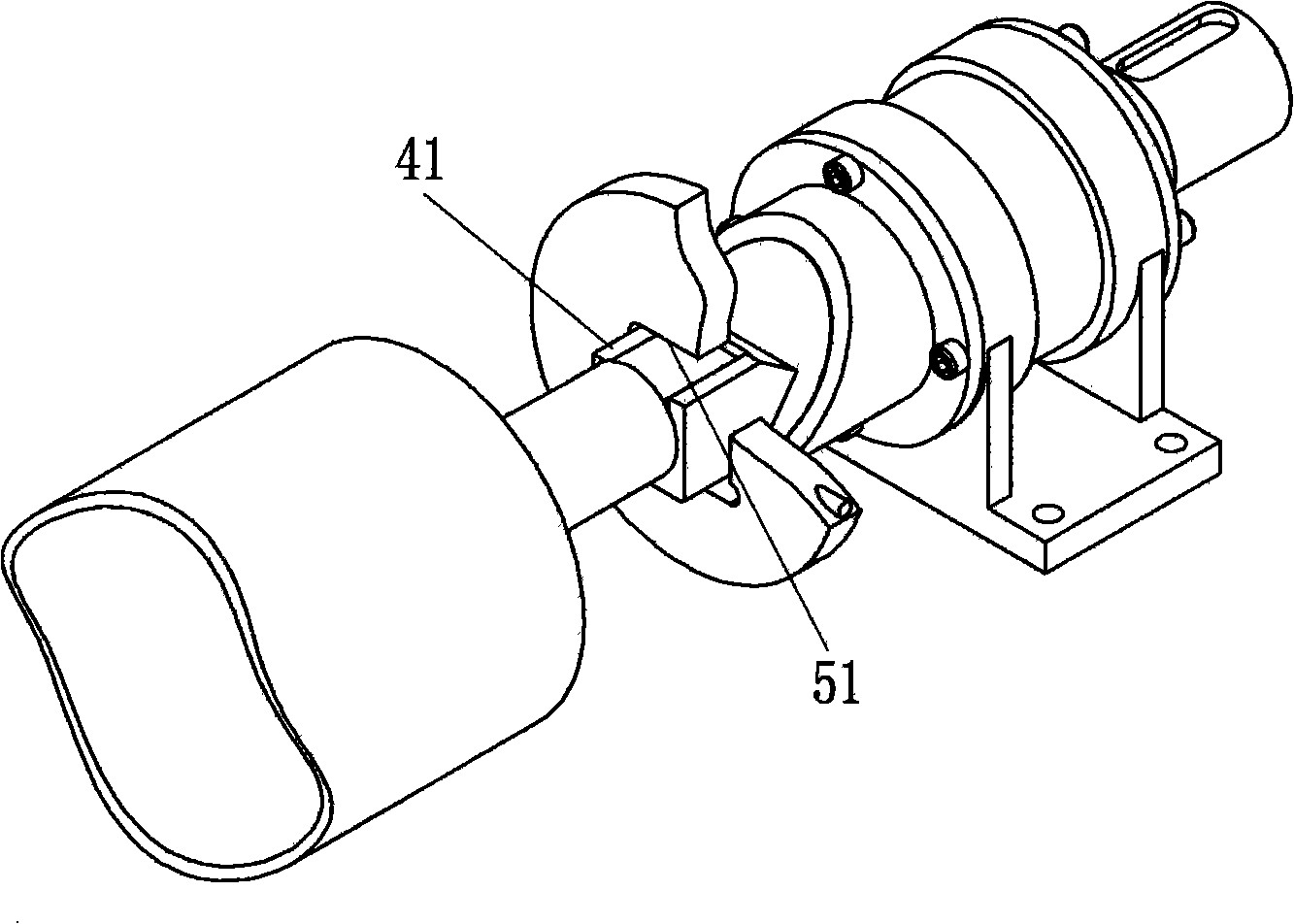
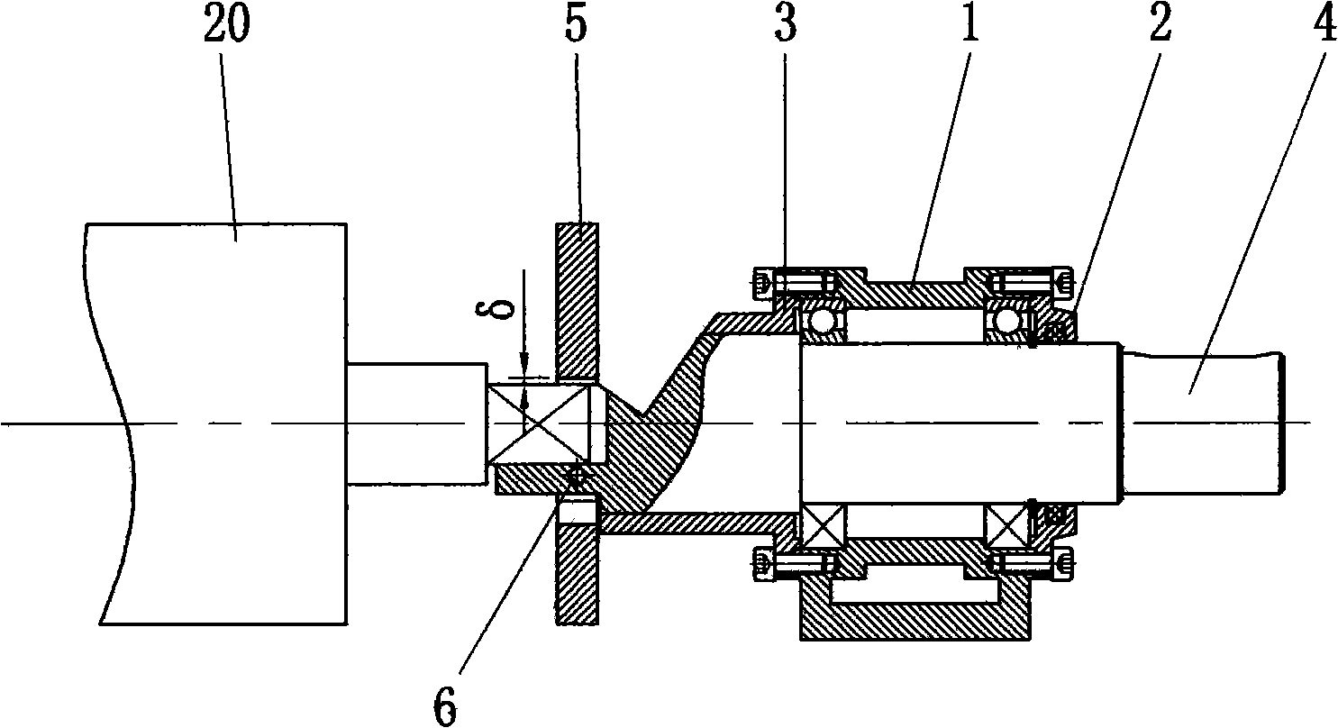
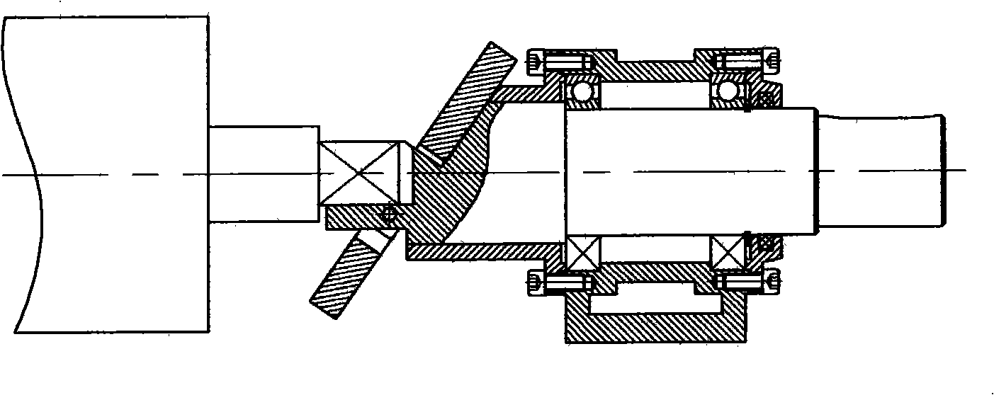
[0025] Such as Figure 5 , Image 6 , Figure 9 , Figure 10 As shown, the shaft 7 is installed on the support 1 through two bearings, a plane 701 and a square groove 702 are processed on one end of the shaft 7, the end cover 2 is installed on one end of the support 1, and the oblique sleeve 3 is installed on the bottom of the support 1. On the other end, the end of the inclined sleeve 3 not in contact with the support 1 is processed into an inclined surface 301 . The guide sleeve 8 is sleeved on the shaft 7, and the inner hole of the guide sleeve 8 has a plane 831, which coincides with the plane 701 on the shaft 7, so that the guide sleeve 8 can only slide axially relative to the shaft 7 and cannot rotate.

[0026] Such as Image 6 , Figure 10 As shown, the guide sleeve 8 is made up of three parts, specifically including an overcoat 81...


PUM


Abstract

The invention relates to a clamping device of a cloth roller on a grey cloth rolling machine, comprising a support, an end cover, an inclined sleeve and a shaft; the shaft is installed on the support by a bearing; the clamping device is characterized in that: one end of the shaft is provided with a plane and a square groove and further equipped with a guide sleeve, the guide sleeve is sheathed on the shaft, the plane of an inner bore of the guide sleeve is coincident with the plane on the shaft and the cylindrical surface of the inner bore of the guide sleeve is partially coincident with the cylindrical surface of the shaft, and one end surface of the guide sleeve is an inclined plane that is not vertical to the axial line of the guide sleeve. Compared with the prior art, the clamping device of the invention has the advantages that: during the rotation of the cloth roller, a square shaft head can not shift in the square groove of the shaft and has no impact and noise; when the shaft rotates till the opening of the square groove faces downwards, the guide sleeve can bear the weight of cloth rolls and the cloth roller, therefore, parts are not easily to be damaged and are durable; the shaft and the guide sleeve are both simple in shape and easy to be processed and the whole device has convenient installation and dismantlement and easy to be maintained.

Description

technical field [0001] The invention relates to a gray cloth rolling machine, in particular to a clamping device for a cloth rolling roller on the gray cloth rolling machine. Background technique [0002] During the work of the gray cloth rolling machine, when the diameter of the cloth roll reaches the specified size, the cloth roll and the cloth rolling roller must be removed from the machine and replaced with a new cloth rolling roller. In the prior art, the clamping device of the cloth rolling roller is as figure 1 , figure 2 , image 3 As shown, the device is mainly composed of a support 1, an end cover 2, an oblique sleeve 3, a square end connecting shaft 4, a chuck 5 and a long pin 6, and the long pin 6 connects the square end connecting shaft 4 and the chuck 5 together. , The square shaft end of the cloth winding roller 20 is placed in the square groove at one end of the square end connecting shaft 4 . The shape of the square end connecting shaft 4 is as follows ...

Claims


Application Information

Patent Timeline
Patent Type & Authority Applications(China)
IPC IPC(8): B65H18/02B65H19/22
Inventor 杨希霞曹波
Owner 杨希霞
Why Eureka
Try Eureka