Vehicle transmission control mechanism assembly testing bench

A technology for automobile gearboxes and operating mechanisms, applied in the field of test benches, which can solve problems such as complex system maintenance, damping force test and control program errors, and troublesome program modification

Active Publication Date: 2008-12-10
WUHU WANLIYANG TRANSMISSION CO LTD
View PDF2 Cites 49 Cited by
  • Summary
  • Abstract
  • Description
  • Claims
  • Application Information

AI Technical Summary

Problems solved by technology

In terms of testing equipment for automobile transmission control mechanism assembly, there is no testing equipment integrating performance and durability in China.
Although there are many test methods and equipment for automobile transmission control mechanism assembly at home and abroad, most of the equipment is controlled by servo motors, and the load system mostly uses weights and cylinders. Not only the test cost is high, but also the load control cannot completely simulate the actual vehicle. State, as the patent No. is CN200410068018.1, and the technical scheme disclosed in the patent titled "Car Transmission Shift Test Bench Control System" adopts computer programming control, and the power system adopts servo motor loading, which has complex control, troublesome program modification and The disadvantage of complex system maintenance is that its load system adopts damping load. Although it claims to provide the damping force under the real vehicle state, there will be certain errors in the testing and control procedures of the damping force, which will affect the testing of the entire system. Many Under the circumstances, it is not possible to fully simulate the actual vehicle state, especially when performing the static basic performance test of the transmission control mechanism assembly, the size of the shift gap and the shift force cannot be realized by simulating the load; another example is the patent number CN200510110178 .2 The patent titled "Test Bench for Automobile Shifter Assembly Performance Test" is only a test bench for testing the life of the synchronizer of the auto transmission

Method used


Image

  • Vehicle transmission control mechanism assembly testing bench

Examples


Embodiment Construction

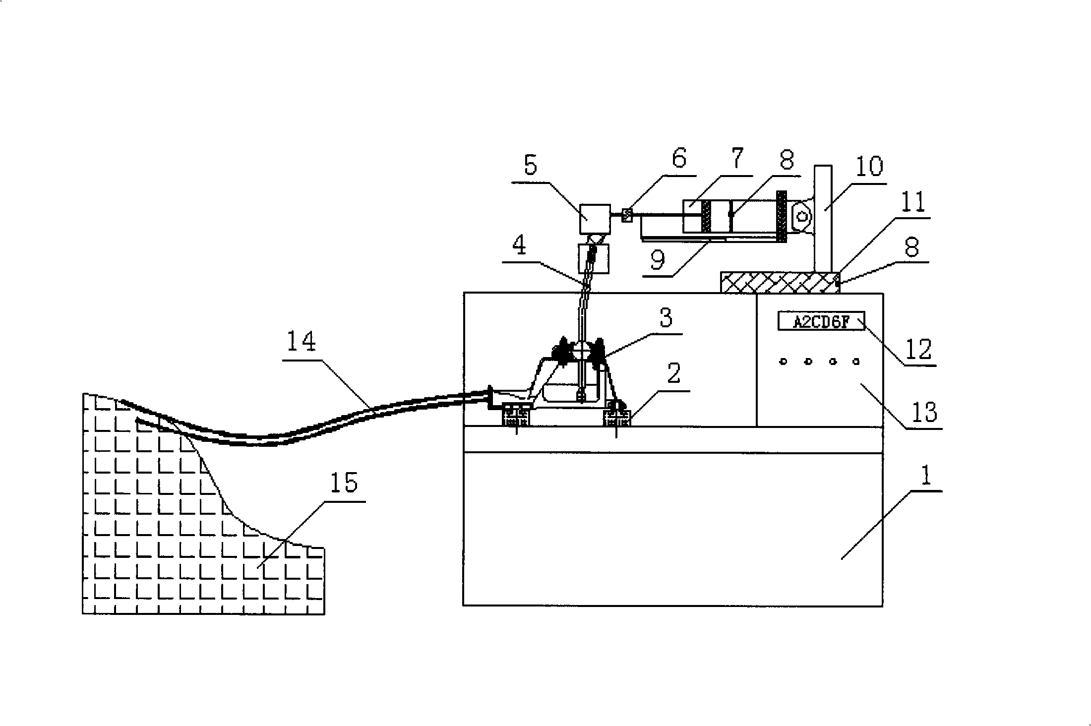
[0016] figure 1 Shown is a schematic diagram of the structure of the test bench for the control mechanism assembly of the automobile transmission. The test bench for the control mechanism assembly of the automobile transmission includes a test bench body 1, which is located in the test bench body 1, and the front end is fixedly installed with a six-direction movable The adjusted installation and adjustment frame 2, the automobile transmission and shifting control mechanism assembly 3 is installed on the installation and adjustment frame 2, the output end of the automobile transmission and shifting operation mechanism assembly 3 is connected with the gearbox 15 through the selection and shifting cable 14, and is located at A PLC control system control frame 13 is installed on the rear side wall of the test bench body 1 , and a cylinder loading system and a load system are arranged above the test bench body 1 .

[0017] The structure of the cylinder loading system is: the gear s...


PUM


Abstract

The invention discloses a test-bed for testing the performances and durability of a shift control mechanism assembly of a vehicle which includes a test-bed body; in the test-bed body, an adjustable mounting adjusting framework with six directions is fixedly arranged at the front end; the shift control mechanism assembly of the vehicle is arranged in the mounting adjusting framework; the output end of the shift control mechanism assembly of the vehicle is connected with a gearbox by selecting and exchanging gearshift lines; the control frame of a PLC control system is arranged on a side wall at the back part in the test-bed body; an air cylinder loading system and a load system are arranged above the test-bed body. The assembly of the test-bed has the following advantages of: 1, being capable of simulating the actual operating condition of the shift control mechanism assembly of the vehicle; 2, being capable of simulating the gear shift and selecting motions on the shift control mechanism assembly of the vehicle; 3, dividing the test-bed controlled by the system into a 'manual' operating mode and an 'automatic' operating mode which can freely and mutually switch; 4, having the function of alarming when the time for gear shift is excessive.

Description

technical field [0001] The invention relates to a test bench for performance and durability testing of an automobile speed change control mechanism assembly. Background technique [0002] The automotive transmission control mechanism assembly is one of the key components of a passenger car, and its performance and service life are directly related to the use and safety performance of the vehicle. However, there is no testing equipment that integrates performance and durability in the testing equipment of the automobile transmission control mechanism assembly. Although there are many test methods and equipment for automobile transmission control mechanism assembly at home and abroad, most of the equipment is controlled by servo motors, and the load system mostly uses weights and cylinders. Not only the test cost is high, but also the load control cannot completely simulate the actual vehicle. State, as the patent No. is CN200410068018.1, and the technical scheme disclosed in...

Claims


Application Information

Patent Timeline
Patent Type & Authority Applications(China)
IPC IPC(8): G01M13/02G01M17/007
Inventor 任建民陈峰农飞飞高宏圣胡滨滕海杰
Owner WUHU WANLIYANG TRANSMISSION CO LTD
Why Eureka
Try Eureka