Method for detecting head wave of sound wave transmission method

A transmission method and sound wave technology, applied in the direction of using sound wave/ultrasonic wave/infrasonic wave to analyze solids, etc., can solve the problems of poor anti-interference ability, decreased efficiency, inappropriate, etc., to achieve strong anti-interference ability, reduce false positive rate, large economy effect of benefit

Inactive Publication Date: 2010-07-21
WUHAN RSM INTELLIGENC GEOTECHN
View PDF4 Cites 0 Cited by
  • Summary
  • Abstract
  • Description
  • Claims
  • Application Information

AI Technical Summary

Problems solved by technology

If the threshold A is set too large, when the amplitude of the acoustic wave is small, the real amplitude of the first wave will be smaller than the threshold A, and then the half-wave with a larger amplitude will exceed the threshold A, which will be judged as the first wave, causing misjudgment
[0010] (2) Poor anti-interference ability
If the threshold A is set too small, when the signal-to-noise ratio of the acoustic waveform is low, the noise may exceed the threshold A and be judged as the first wave, resulting in misjudgment
[0011] Misjudgment may have extremely serious consequences, so it is necessary to manually adjust the threshold A frequently, resulting in a significant drop in efficiency
[0012] In fact, judging the first wave based on the acoustic waveform should be based on the curve characteristics of the waveform. The scaling up or down of the amplitude of the acoustic waveform does not lead to changes in the identification of the first wave. It is obviously inappropriate to only consider the amplitude information

Method used


Image

  • Method for detecting head wave of sound wave transmission method
  • Method for detecting head wave of sound wave transmission method
  • Method for detecting head wave of sound wave transmission method

Examples


Embodiment 1

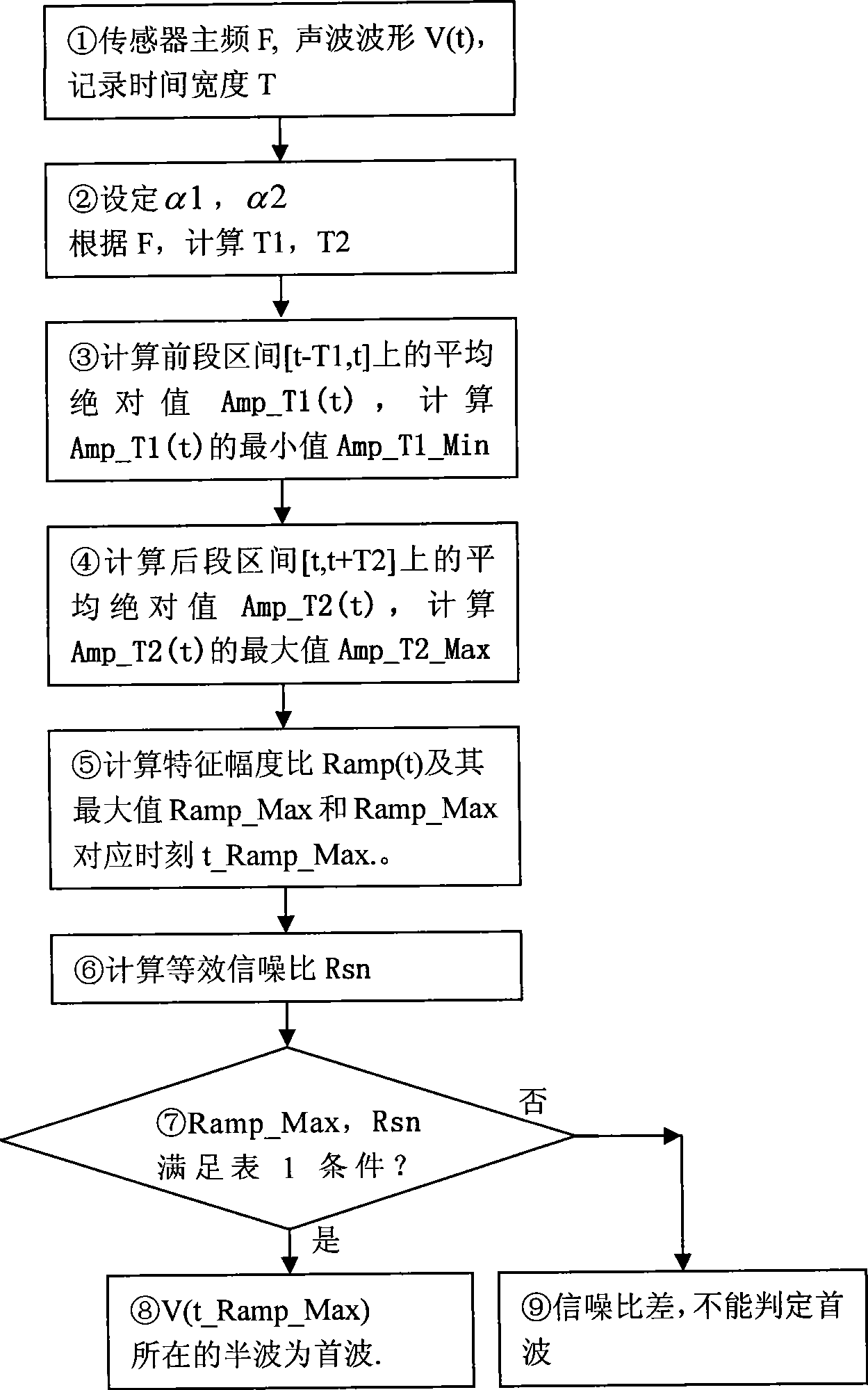
[0037] according to figure 1 It can be seen that the steps of a first wave detection method are:

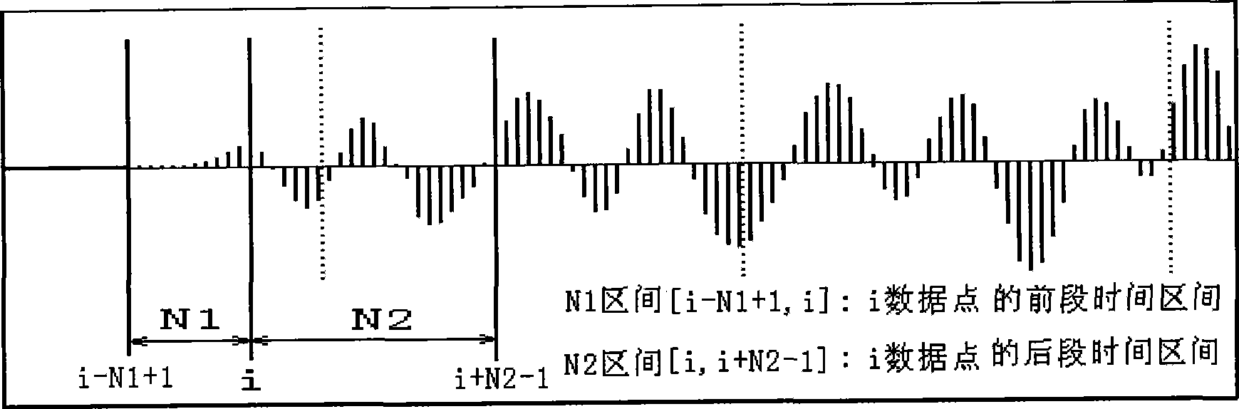
[0038] ① Determine the resonant frequency of the transmitting sensor and determine the time interval of the acoustic waveform recorded by the acoustic wave instrument: the resonant frequency F of the transmitting sensor is the nominal frequency of the transmitting sensor; the time interval width T of the acoustic waveform V(t) recorded by the acoustic wave instrument. For digital signals, the sampling time interval of the digital acoustic wave instrument A total of N sound wave sampling data V(i), [i=0, 1, ... N-1] are obtained by sampling in the T period of time,

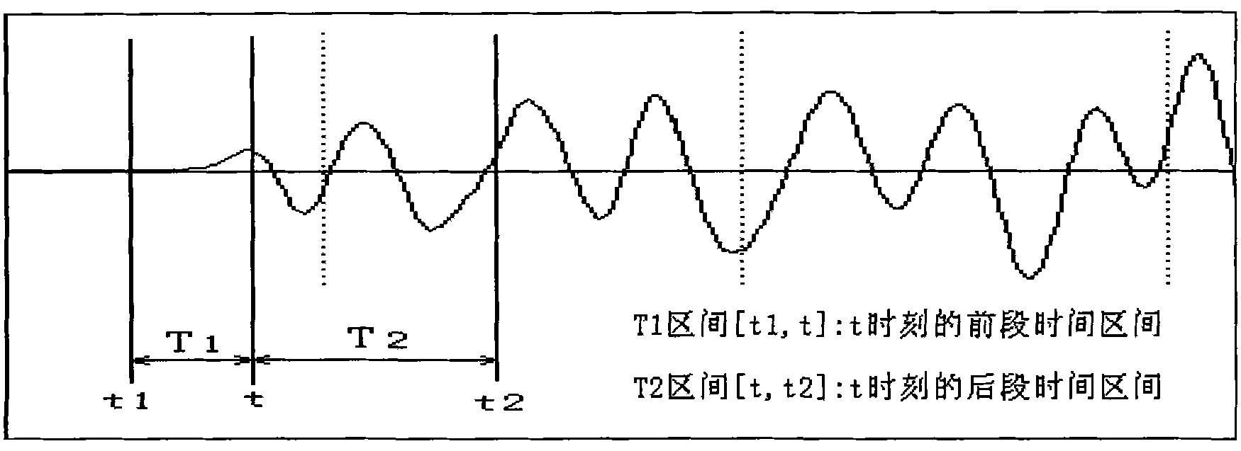
[0039] ② Determine the width of the previous time interval and the width of the later time interval: the time interval [t1, t] with time t as the end time is called the previous time interval at time t, and the time interval [t, t2] with time t as the start time ] is called the later period of time at this moment...

Embodiment 2

[0081] Embodiment 2: Taking the digital signal sampled and acquired when detecting the integrity of a foundation pile by the acoustic wave transmission method as an example, the amplitude of the first wave of the acoustic waveform in this example is small, and it is easy to misjudge the first wave by using the method of setting the amplitude threshold A. Follow the Figure 4 The steps of implementing the detection method of the present invention:

[0082] ① Determine the main frequency F of the transmitting sensor, and determine the time interval T of the acoustic waveform recorded by the acoustic wave instrument:

[0083] Acoustic sensor main frequency F=30KHz, sampling time interval The N=512 acoustic waveform data obtained by sampling, V(i)[i=0, 1, ... 511], see Figure 5 Medium V(i) curve.

[0084] ② Determine the width of the previous period of time interval and the width of the latter period of time interval:

[0085] Set α1=1.0, α2=2.0, α1≦α2.

[0086] According t...

Embodiment 3

[0100] Embodiment 3: Take the digital signal collected indoors as an example. In this example, the signal-to-noise ratio of the acoustic waveform is poor, and it is easy to misjudge the first wave by using the method of setting the amplitude threshold A. Follow the Figure 4 The steps of implementing the detection method of the present invention:

[0101] ① Determine the main frequency F of the transmitting sensor, and determine the time interval T of the acoustic waveform recorded by the acoustic wave instrument:

[0102] Acoustic sensor main frequency F=50KHz, sampling time interval The N=512 acoustic waveform data obtained by sampling, V(i)[i=0, 1, ... 511], see Figure 6 Medium V(i) curve.

[0103] ② Determine the width of the previous period of time interval and the width of the latter period of time interval:

[0104] Set α1=1.0, α2=2.0, α1≦α2.

[0105] According to F=50KHz=50000Hz, sampling time interval Calculate N1=20, N2=40 according to formula (7)(8):

[0...


PUM


Abstract

The invention discloses a head wave acoustic transmission detection method. The width of a front period time interval and the width of a back period time interval are determined according to the resonance frequency of an acoustic sensor; the average absolute value of the acoustic waveform in the front period time interval is calculated, and the average absolute value in the front period time interval is recorded; the average absolute value of the acoustic waveform at the back period time interval of every time is calculated, and the maximum value of the average absolute value in the back period time interval is recorded; the characteristics amplitude ratio of every time is calculated, and the maximum value of the characteristic amplitude ratio is recorded; the equivalent signal noise rateis calculated; the existence of the head wave is judged according to the numerical relation between the maximum value of the characteristics amplitude ratio and the equivalent signal noise rate; under the condition that the existence of the head wave is judged, the half-wave of the corresponding data of the maximum value is the head wave obtained through the detection. The head wave acoustic transmission detection method has the advantages of easy operation, convenient operation and strong anti-interference ability during the detection of the head wave. The detection efficiency is improved, and obvious economical benefits are provided.

Description

technical field [0001] The invention belongs to the detection method of the first wave of the acoustic wave in the technology of using the acoustic wave transmission method to test the acoustic parameters of the rock-soil medium by using the acoustic wave instrument, and is applied to the detection of the sound wave velocity of the rock-soil medium by the acoustic wave instrument and the detection of the integrity of the pile body of the poured foundation pile by the acoustic wave instrument . Background technique [0002] It is a widely used technology to detect the acoustic wave velocity and the first wave amplitude of the rock and soil medium by the acoustic wave transmission method using the acoustic wave instrument. For example, the detection of the acoustic wave velocity of the foundation pile body medium and the amplitude of the first wave of the sound wave are used to determine the integrity of the foundation pile, see "Technical Specifications for Building Foundatio...

Claims


Application Information

Patent Timeline
Patent Type & Authority Patents(China)
IPC IPC(8): G01N29/04G01N29/07G01N29/12
Inventor 张杰胡纯军邹宇李祺
Owner WUHAN RSM INTELLIGENC GEOTECHN
Why Eureka
Try Eureka