Apparatus for measuring acceleration by double optical beams, optical fibers and light traps

A dual-beam, acceleration technology, applied in the direction of measuring acceleration, measuring device, speed/acceleration/impact measurement, etc., can solve the problems of error, affecting the shape of the manipulator, reducing the test accuracy and service life, etc., so as to improve the service life and avoid deformation effect

Inactive Publication Date: 2008-12-10
ZHEJIANG UNIV
View PDF0 Cites 16 Cited by
  • Summary
  • Abstract
  • Description
  • Claims
  • Application Information

AI Technical Summary

Benefits of technology

In this new type of accelerometer used for motion tracking purposes, there are several technical improvements compared to previous designs such as being able to measure both linear (L) movement and rotational movements simultaneously without any issues like wear or damage caused during use. Additionally, it allows for more accurate measurements than existing devices while still maintaining its durability when installed properly.

Problems solved by technology

This patented technical problem addressed in this patents relates to improving the stability and reliability of accelerometer systems used during research or development efforts related to analyzing how different materials behave upon impacts from external sources like collisions between objects.

Method used


Image

  • Apparatus for measuring acceleration by double optical beams, optical fibers and light traps
  • Apparatus for measuring acceleration by double optical beams, optical fibers and light traps

Examples


Embodiment Construction

[0015] Further illustrate the present invention below in conjunction with accompanying drawing.

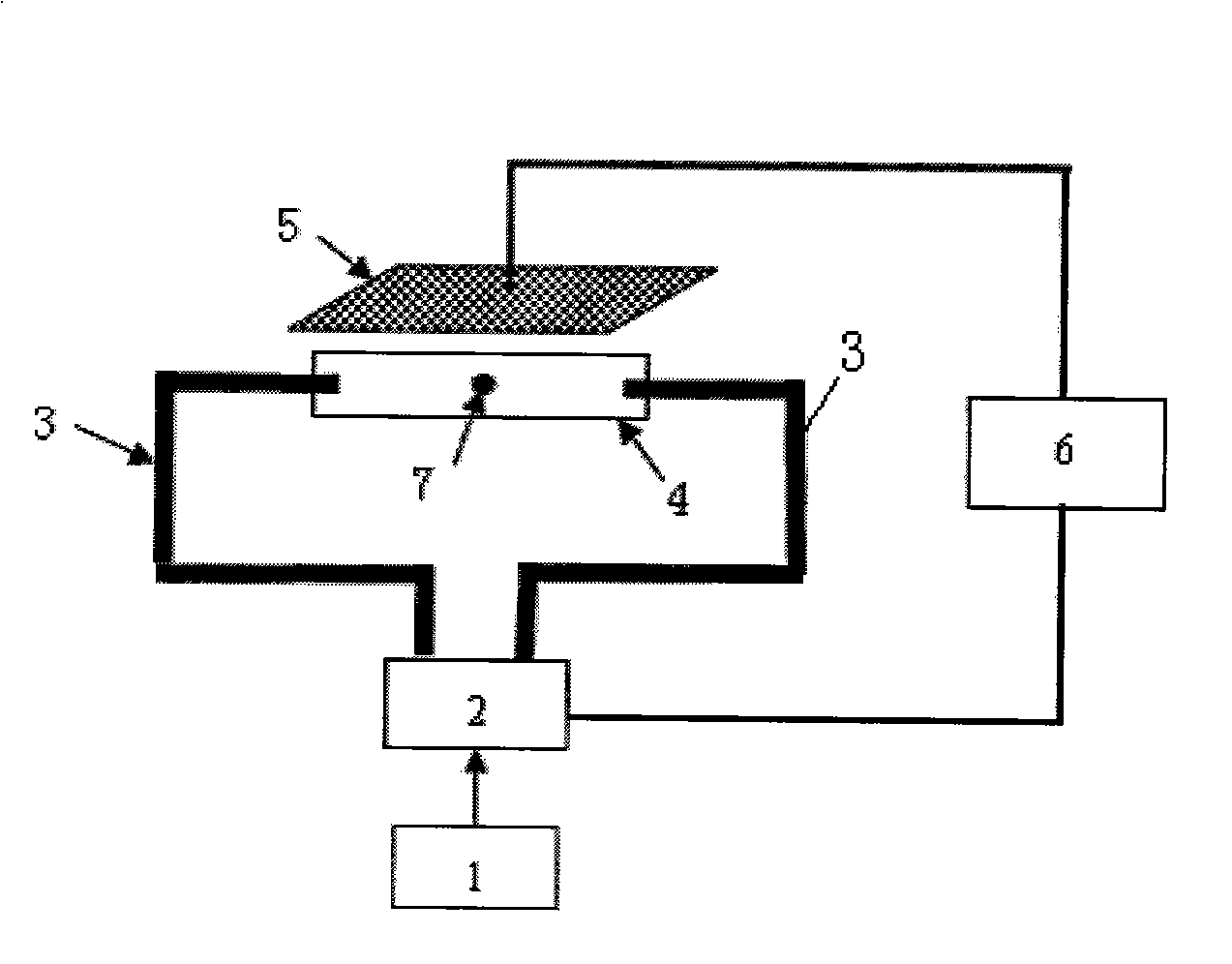
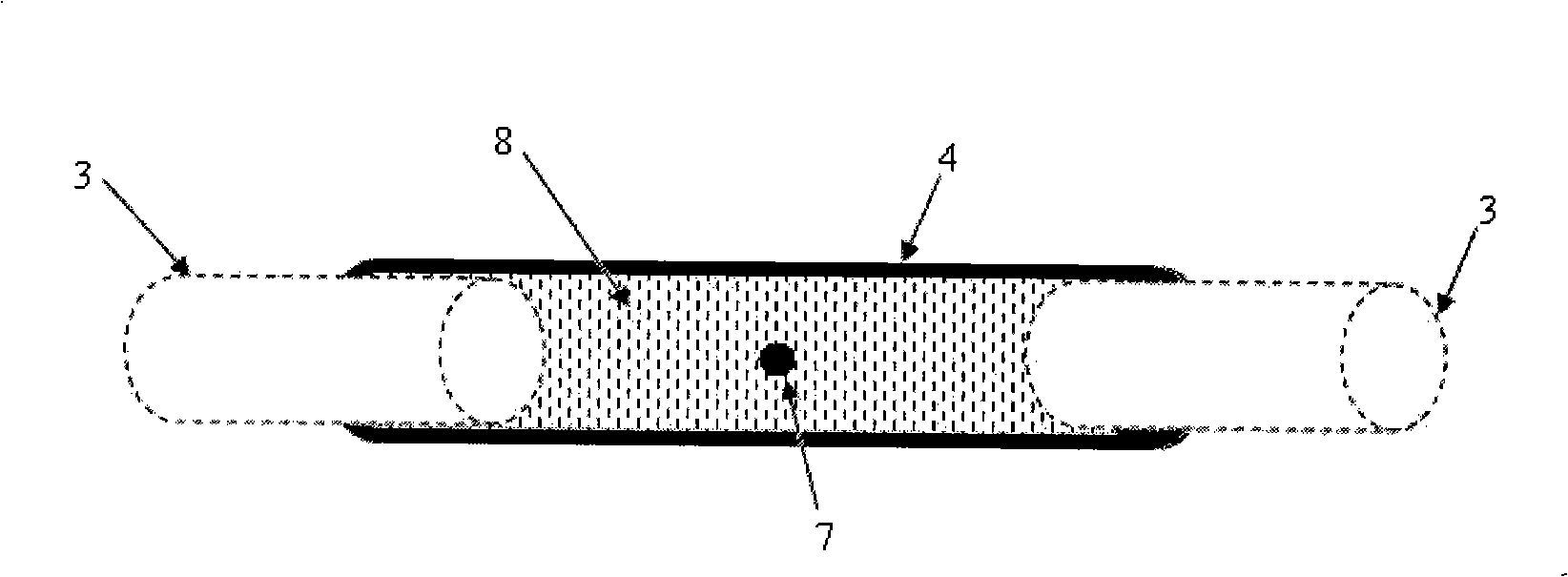
[0016] refer to figure 1 , figure 2 , a device for measuring acceleration using a double-beam fiber optic trap, including a laser 1 fixed on a substrate, a light intensity modulator 2, two single-mode optical fibers 3, a glass capillary 4, a photoelectric image detector 5 and a processor 6, the laser 1 The emitted light is modulated by the light intensity modulator 2 into two beams of light with the same light intensity, and then input into two single-mode optical fibers 3 respectively. The diameter of the output end face of the mode fiber 3 matches the caliber of the glass capillary 4, so that the beams emitted from the end faces of the two single mode fibers 3 can be precisely aligned. The output end faces of the two single-mode optical fibers 3 are spaced apart, usually, the space is 100-800 microns. Place a spherical SiC particle 7 in the glass capillary 4, the radius of t...


PUM

PropertyMeasurementUnit
Radiusaaaaaaaaaa

Abstract

The invention discloses a device which uses a dual-beam optical fiber light trap to measure acceleration. The device comprises an optical maser, a light intensity modulator, two single mode fibers, a capillary glass tube, a photonics image detector and a processor which are arranged on a substrate; wherein, light sent out from the optical maser is modulated into two beams of light with same intensity and then respectively input in the two single mode fibers; and the output ends of the two single mode fibers are respectively fixed at the two ends of the capillary glass tube; and the caliber of the capillary glass tube is matched with the output end of the single mode fiber; a ball-shaped SiC particle is arranged in the capillary glass tube. The device provided by the invention is fixed on the main body of a measured object, and when the main body of the measured object is in accelerated motion along the direction of optical axis, the particle is going to deviate from the original balance position. The photonics image detector measures the position of the particle, and a corresponding adjustment value can be worked out by the processor, and then the light intensity modulator changes the output light intensities of the two beams of light according to the measured position of the particle and the obtained adjustment value to let the particle return to the original balance position. According to the light intensity differences of the light intensity modular, the processor works out gained acceleration.

Description


Claims


Application Information

Patent Timeline
Owner ZHEJIANG UNIV
Why Eureka
Try Eureka