Double-insert feeding control structure of mosaic wheel

A technology of feeding control and chip insertion, which is applied to conveyor objects, transportation and packaging, etc., can solve the problems of waste of abrasive belt material, influence of chip insertion efficiency, and inability to obtain the performance of the effect, and achieve the effect of precise and reasonable transmission structure.

Active Publication Date: 2021-03-12
广东益鼎机器人有限公司
View PDF9 Cites 0 Cited by
  • Summary
  • Abstract
  • Description
  • Claims
  • Application Information

AI Technical Summary

Problems solved by technology

[0002] Flower impellers and louver wheels are all processed by cutting abrasive belts and inserting them side by side. With the development of technology, laser cutting has become more mature and the efficiency of laser cutting is also higher. However, the existing inserting device is a single inserting device. The structure, that is, the motor or cylinder drives the mechanical arm to clamp the cut sand pieces and insert them into the sheet arrangement seat one by one to form a flower impeller. This structure can only insert a single piece at a time, and the efficiency is limited, especially the current laser cutting. , affected by the efficiency of the insert, the efficacy cannot be reflected; at the same time, when the insert is required to be a notched rectangle, the cutting abrasive belt adopts "Z" cutting, and a single insert cannot be adapted to the application, resulting in a serious waste of abrasive belt material

Method used


Image

  • Double-insert feeding control structure of mosaic wheel
  • Double-insert feeding control structure of mosaic wheel
  • Double-insert feeding control structure of mosaic wheel

Examples


Embodiment

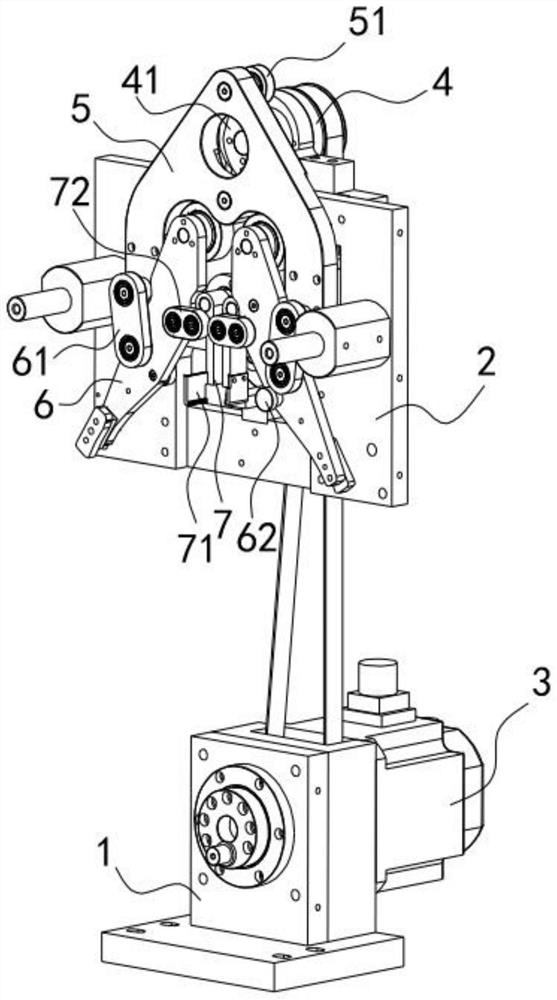
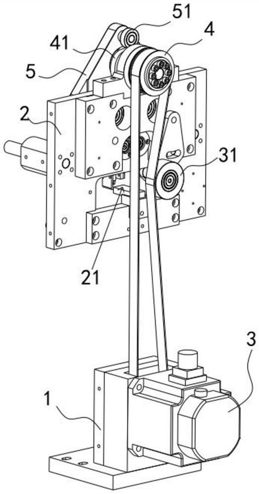
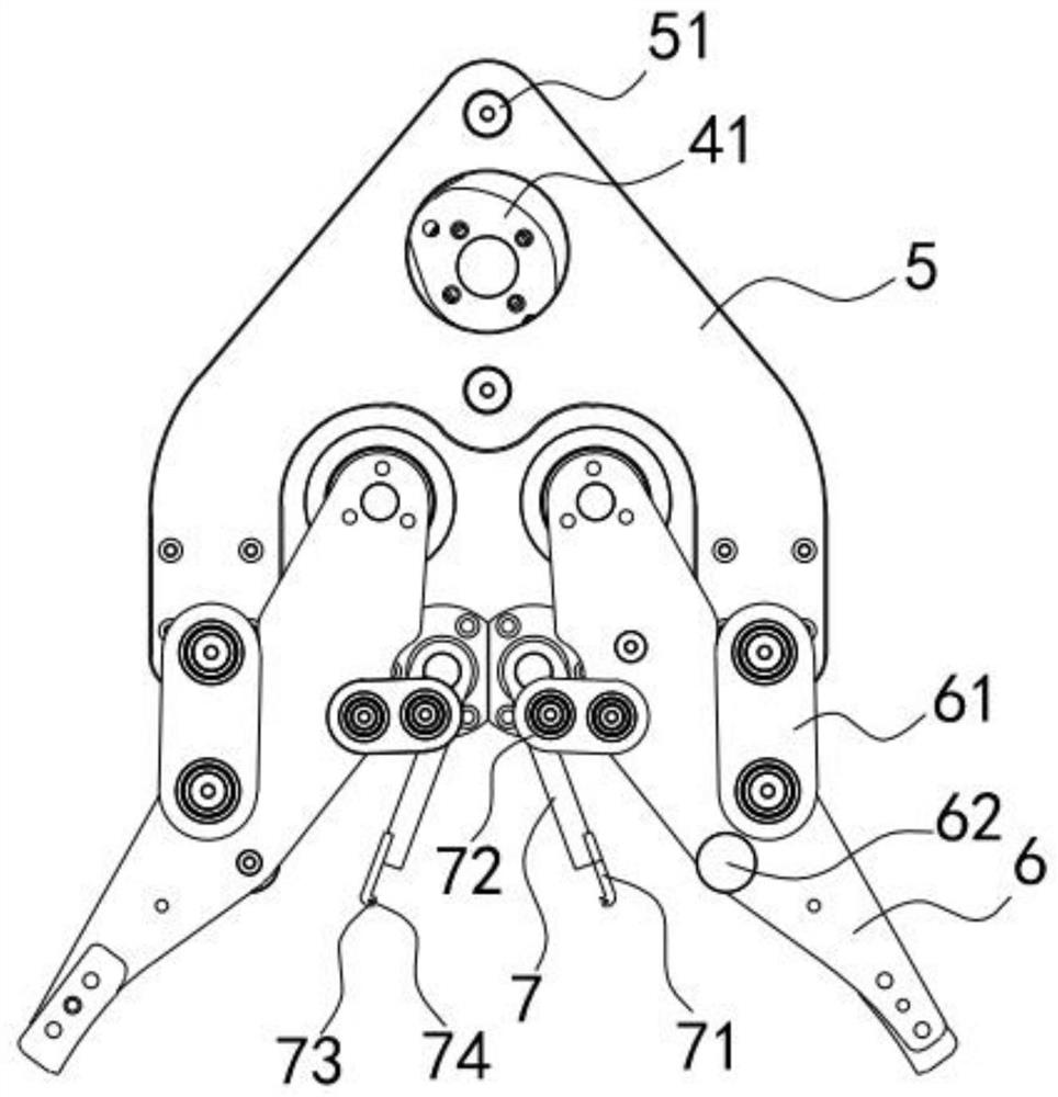
[0028] Such as Figures 1 to 3 As shown, the flower impeller double insert feeding control structure includes a base 1 and a drive base plate 2, a drive motor 3 is fixedly installed on the base 1, a drive shaft 4 is fixedly installed on the drive base plate 2, and the drive shaft 4 and the drive motor 3 transmission connection; also includes drive cam 41, drive cam 41 is coaxially connected with drive shaft 4; also includes movable plate 5, movable plate 5 top is provided with transmission wheel 51, and transmission wheel 51 contacts with drive cam 41, and transmission wheel 51 drives the movable plate 5 to move up and down with the rotation of the drive cam 41; it also includes the main transmission rod 6, one end of the main transmission rod 6 is hinged with the drive substrate 2, and the middle part of the main transmission rod 6 is driven and matched with the movable plate 5 through the hinged main transmission block 61 , the two ends of the main transmission block 61 are ...


PUM


Abstract

The invention discloses a double-insert feeding control structure of a mosaic wheel. The structure comprises a drive cam, a movable plate and a feeding limiting plate, wherein the drive cam is in coaxial driving connection with a drive shaft; a transmission wheel is arranged at the top of the movable plate, is in contact fit with the drive cam, and drives the movable plate to move up and down along with the rotation of the drive cam; and the feeding limiting device comprises limiting drive rods which are symmetrically arranged and limiting clamps arranged at the bottoms of the limiting drive rods, one ends of the limiting drive rods are hinged to a driving base plate, the limiting drive rods are in transmission fit with a main transmission rod through hinged limiting transmission blocks, and the two ends of the limiting transmission blocks are hinged to the middle of the main transmission rod and the limiting drive rods. According to the structure, a driving motor drives the drive camto rotate, linkage of the main transmission rod and the limiting drive rods on the driving base plate is achieved, opening and closing movement of the limiting clamps is achieved, the material takingaction of a material taking device can be conveniently matched, the whole structure only needs to be driven by one driving motor, and the transmission structure is precise and reasonable.

Description

technical field [0001] The invention relates to the field of flower impeller insert structure, in particular to a flower impeller double insert feeding control structure. Background technique [0002] Flower impellers and louver wheels are all processed by cutting abrasive belts and inserting them side by side. With the development of technology, laser cutting has become more mature and the efficiency of laser cutting is also higher. However, the existing inserting device is a single inserting device. The structure, that is, the motor or cylinder drives the mechanical arm to clamp the cut sand pieces and insert them into the sheet arrangement seat one by one to form a flower impeller. This structure can only insert a single piece at a time, and the efficiency is limited, especially the current laser cutting. , affected by the efficiency of the insert, the efficacy cannot be reflected; at the same time, when the insert is required to be a notched rectangle, the cutting abrasi...

Claims


Application Information

Patent Timeline
Patent Type & Authority Applications(China)
IPC IPC(8): B65G47/90
CPCB65G47/90
Inventor 吴国章
Owner 广东益鼎机器人有限公司
Why Eureka
Try Eureka