Projection display
A display device and projection technology, which is applied to the image reproducer of the projection device, projection device, optics, etc., can solve the problems of uneven illumination and inability to obtain contrast.
Active Publication Date: 2010-08-25
SEIKO EPSON CORP
View PDF1 Cites 0 Cited by
- Summary
- Abstract
- Description
- Claims
- Application Information
AI Technical Summary
Problems solved by technology
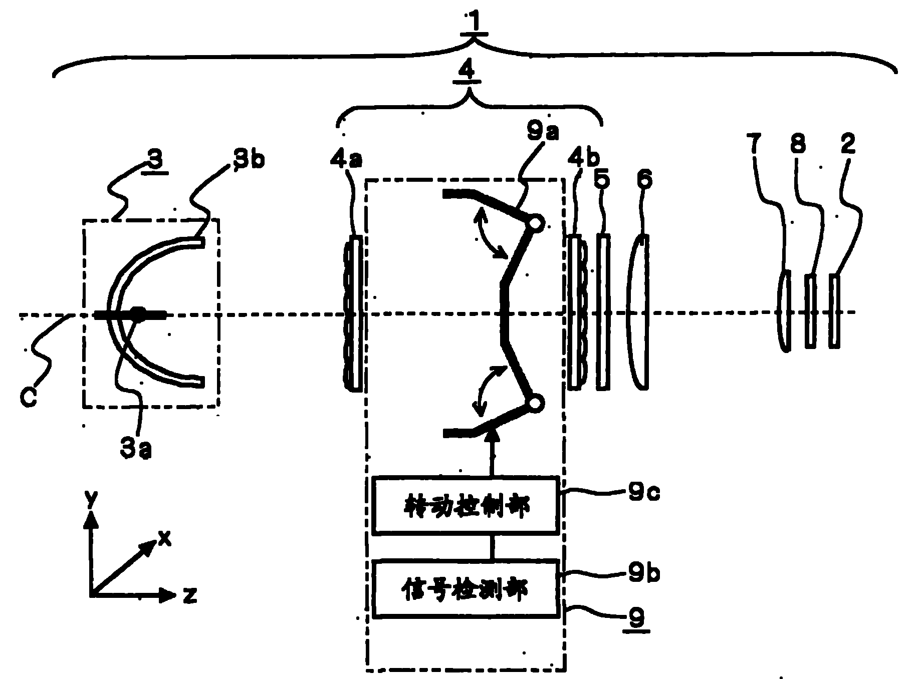
In Patent Document 1, when the shape of the front end of the shading plate has a rectangular surface in the direction perpendicular to the shading plate, in the vicinity of the first lens array, when the front end of the shading plate is located in the second lens array in the direction of rotation of the shading plate When the center of curvature of the shading plate is at the center of the curvature, the rectangular surface of the shading plate is imaged on the light valve, so there is a problem of linear uneven illuminance in the direction of rotation on the light valve and in the direction perpendicular to the direction of the optical axis.
In addition, depending on the shape of the tip of the shade, there is also a problem that sufficient contrast cannot be obtained.
Method used
View moreImage
Smart ImageViewing Examples
Examples
Embodiment approach 1
Embodiment approach 2
Embodiment approach 3
Login to View More PUM
 Abstract
The invention provides a projection display that achieves continuous light amount control with ease and without causing unevenness of illumination of light applied to a light valve responsive to a video signal, thereby allowing constant image display with satisfactory contrast. The projection display of the invention includes a light valve (2); a light source (3a) generating light applied to the light valve (2); an integrator lens (4) provided on an optical path between the light source (3a) and the light valve (2) and making uniform the illumination distribution of light applied from the light source (3a) to the light valve (2); and a light amount control system (9) provided on the optical path and including a turning mechanism (9a) which turns like a set of double doors in order to adjust the amount of light applied from the light source (3a) to the light valve (2). The turning mechanism (9a) is bent into a V shape in a direction to reduce the amount of light (to block the light).
Description
technical field The present invention relates to a projection display device having a light quantity adjustment mechanism for adjusting the light quantity of light irradiated on a light valve according to a video signal. Background technique In a projection display device, there is a darker image display due to light leakage from various optical elements constituting the optical system, such as a guide optical system and a projection lens, and stray light (unwanted light) generated at the optical elements. Not dark enough to get a higher contrast tendency. Especially when an image is projected on a screen in a dark room, if the dark image cannot be displayed dark enough, it will give the viewer the impression that the contrast is insufficient. In particular, in projection display devices using liquid crystal light valves, the liquid crystal light valves block transmitted light due to the polarization characteristics of light, but cannot completely block transmitted light, a...
Claims
Login to View More Application Information
Patent Timeline
 Patent Type & Authority Patents(China)
IPC IPC(8): G03B21/14H04N9/31
CPCH04N9/3197H04N9/3152G03B21/14
Inventor 山田旭洋别所智宏大上户晃高桥素男
Owner SEIKO EPSON CORP
Features
- R&D
- Intellectual Property
- Life Sciences
- Materials
- Tech Scout
- Unparalleled Data Quality
- Higher Quality Content
- 60% Fewer Hallucinations
Learn More Browse by: Latest US Patents, China's latest patents, Technical Efficacy Thesaurus, Application Domain, Technology Topic, Popular Technical Reports.
© 2025 PatSnap. All rights reserved.Legal|Privacy policy|Modern Slavery Act Transparency Statement|Sitemap|About US| Contact US: help@patsnap.com


