Pressure-vaccum machine

A technology of blowing suction machine and main machine, which is applied in the direction of vacuum cleaner, mechanical equipment, application, etc., can solve the problems of unfavorable storage of blowing suction machine, inconvenient assembly of volute and main casing, inconvenient assembly, etc., and achieves convenient and fast installation and matching. , Conducive to collection and storage, the effect of safe working performance

Active Publication Date: 2008-12-17
POSITEC POWER TOOLS (SUZHOU) CO LTD
View PDF1 Cites 29 Cited by
  • Summary
  • Abstract
  • Description
  • Claims
  • Application Information

AI Technical Summary

Problems solved by technology

[0003] The trigger button of the above-mentioned safety interlock mechanism can slide freely between the first position and the second position when the volute is separated from the main casing. The first position is the position where the switch is closed, and the second position is where the switch triggers the motor to work. position, only when the trigger button is at the first position, the volute can be installed and connected to the main casing, when the trigger button is at the second position, the volute cannot be installed and mated with the main casing, which makes the volute and the main casing It is inconvenient to assemble; and, the safety interlock mechanism is set between the volute and the main casing, and the volute must be installed on the blowpipe or suction pipe of the blower to meet the different working modes of blowing and suction. This increases the production cost; of course, one volute can also be installed, but the volute is connected with the blowpipe and the suction pipe in a detachable manner. Conducive to the storage of the blower

Method used


Image

  • Pressure-vaccum machine
  • Pressure-vaccum machine
  • Pressure-vaccum machine

Examples


Embodiment Construction

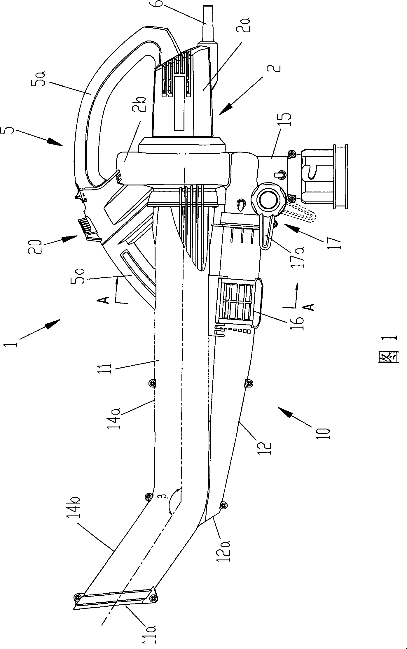
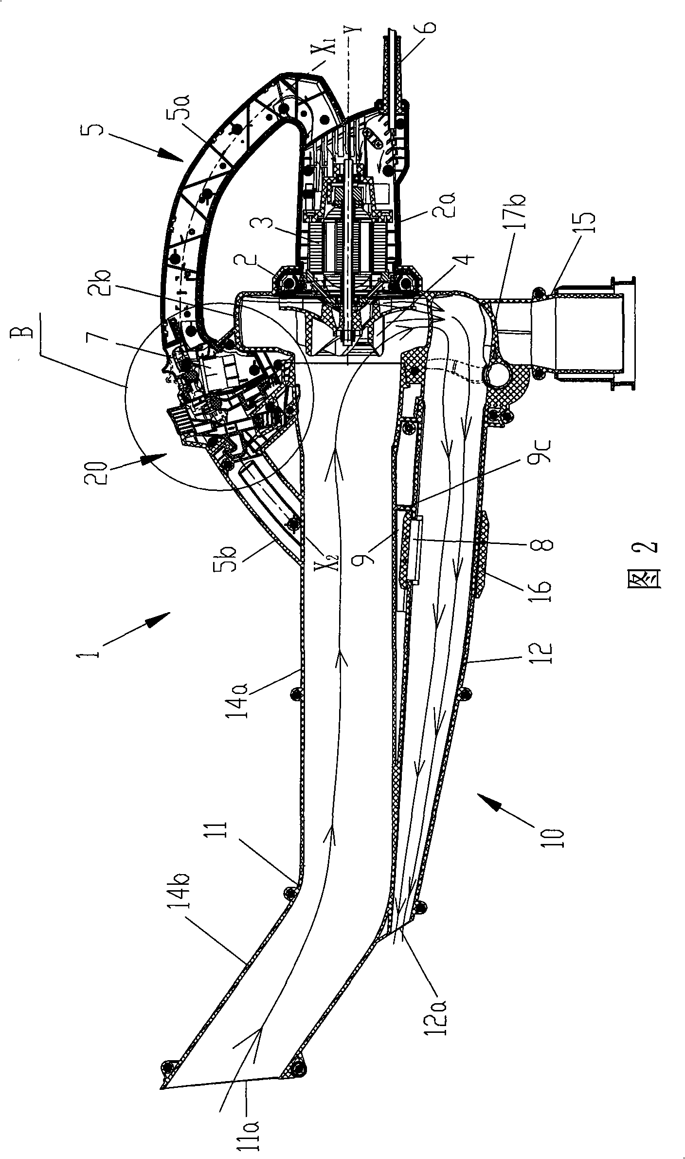
[0037] The disclosure of the present invention discloses a portable blowing and aspirating machine that can be operated with one hand. The blowing and aspirating machine can be switched between two different working modes of blowing and inhaling. The operator only needs to make simple and quick adjustments to quickly realize Blow-suction conversion can also facilitate the cleaning and maintenance of the fan and volute, and can ensure that the blower-suction machine can work in a safe state in both blowing and suction working modes, and it is extremely convenient to assemble, light in structure and easy to operate .

[0038] Referring to Fig. 1 and Fig. 2, the blower 1 is provided with a main body casing 2, which includes a motor casing 2a accommodating a motor 3 and a volute 2b accommodating a fan 4, and the impeller of the fan 4 has an effect on the leaves under high-speed rotation. The function of crushing, the motor casing 2a is fixedly connected with the volute 2b, the rea...


PUM


Abstract

The invention relates to a portable blowing and suction machine, comprising a main unit shell, a motor arranged in the shell, a fan which is driven to rotate by the motor, a switch for controlling the rotation of the motor, a blowing and suction accessory which is connected with the main unit shell in a detachable way and a safety mutual interlocking gear arranged between the blowing and suction accessory and the main unit shell; the safety mutual interlocking gear comprises a trigger gear which can motivate a switch only when the blowing and suction accessory is connected with the main unit shell and a lock device for locking the blowing and suction accessory on the main unit shell when the motor is started; the safety mutual interlocking gear further comprises a slide block, when the blowing and suction accessory is separated from the main unit shell, the slide block can restrict the movement of the trigger gear, thus facilitating the installation and connection of the blowing and suction accessory and the main mechanism.

Description

technical field [0001] The invention relates to a hand-held operating device, in particular to a portable blower provided with a safety interlock mechanism. Background technique [0002] The patent specification of U.S. Patent No. US5604954 discloses a blower with a safety interlock mechanism. The safety interlock mechanism is arranged between the volute housing the fan and the main casing. When the volute is blocked by dust such as branches and leaves, it is necessary to clean and maintain the volute and the fan in time; the safety interlock mechanism includes a trigger button, which can only be activated when the volute is connected to the main casing The switch starts the motor to work, and a locking device is used to lock the volute on the main casing when the motor is started, so that the volute cannot be removed from the main casing under the normal working condition of the blower motor. When the switch is turned off and the motor stops rotating, the volute and other ...

Claims


Application Information

Patent Timeline
Patent Type & Authority Applications(China)
IPC IPC(8): A47L5/14E01H1/08F16P3/08H01H3/20
Inventor 王其彬
Owner POSITEC POWER TOOLS (SUZHOU) CO LTD
Why Eureka
Try Eureka