
Ground-controlled hydraulic pulsing device and application thereof

A hydraulic pulse and ground control technology, applied in vibration generating devices, production fluids, wellbore/well components, etc., can solve problems such as difficulty in adapting to oilfield environment, difficult adjustment of shock frequency, poor applicability, etc., and achieve safe and reliable working performance. , good applicability and simple structure

Active Publication Date: 2020-10-30
CHINA UNIV OF PETROLEUM (EAST CHINA)
View PDF7 Cites 2 Cited by
  • Summary
  • Abstract
  • Description
  • Claims
  • Application Information

AI Technical Summary

Problems solved by technology

This process uses the traditional hydraulic pulse to unplug the oil field, the impact frequency is not easy to adjust, and it is difficult to adapt to different oil field environments
[0005] In view of this, it is very necessary to design a hydraulic pulse device suitable for different oil field environments, which can effectively avoid the problems of poor applicability and complicated operation of traditional hydraulic pulse technology in various oil fields

Method used


Image

  • Ground-controlled hydraulic pulsing device and application thereof

Examples


Embodiment 1

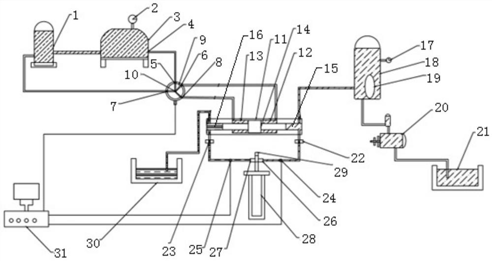
[0037] like figure 1 As shown, this embodiment provides a hydraulic pulse device for ground control, including a frequency conversion servo pulse device and a constant pressure liquid supply device. The frequency conversion servo pulse device includes a hydraulic oil tank 1, a hydraulic pump 3, a frequency conversion servo control valve 9 and a power The converter 11 and the hydraulic oil tank 1 are respectively connected to the oil pressure pump 3 and the frequency conversion servo control valve 9, the oil pressure pump 3 is connected to the frequency conversion servo control valve 9 through the oil pressure pump port 4, and the frequency conversion servo control valve 9 is connected to the power converter 11;

[0038] The constant pressure liquid supply device includes a water storage tank 21, a water injection pump 20 and a pressure accumulator 18. One end of the water injection pump 20 is connected to the water storage tank 21, and the other end is connected to the pressure...

Embodiment 2

[0050] A ground control hydraulic pulse device, the structure is as described in embodiment 1, the difference is that a pressure gauge 17 is arranged on the pressure accumulator 18, and the pressure gauge 17 is connected to the high-pressure air bag 19, which is convenient for observing the pressure in the high-pressure air bag 19, and then By adjusting the liquid capacity in the pressure accumulator 18 to adjust the impact strength of the hydraulic pulse, the pressure in the pressure accumulator 18 is stored as 40MPa.

Embodiment 3

[0052] A ground control hydraulic pulse device, the structure is as described in Embodiment 2, the difference is that the pressure storage of the pressure accumulator 18 is 150MPa, and the pressure gauge 2 is set on the oil pressure pump 3, which is convenient for observing the oil pressure.


PUM


Abstract

The invention relates to a ground-controlled hydraulic pulsing device and application thereof, and belongs to the technical field of oil production process. The device comprises a variable frequency servo pulsing device and a constant pressure liquid supply device. The variable frequency servo pulsing device comprises a hydraulic oil tank, a oil hydraulic pump, a variable frequency servo controlling valve, and a power converter. The hydraulic oil tank is respectively connected with the oil hydraulic pump and the variable frequency servo controlling valve. The oil hydraulic pump is connected with the variable frequency servo controlling valve, and the variable frequency servo controlling valve is connected with the power converter. The constant pressure liquid supply device comprises a water storage tank, a water injection pump, and a pressure reservoir. One end of the water injection pump is connected with the water storage tank, and the other end of the water injection pump is connected with the pressure reservoir. The pressure reservoir is connected with one end of the power converter. The ground-controlled hydraulic pulsing device is placed on the ground, which is rapid and convenient for operation, maintenance and detection in field application in the construction, and the frequency of hydraulic pulse can be adjusted to adapt to different oil field environment.

Description

technical field [0001] The invention relates to a ground control hydraulic pulse device and its application, and belongs to the technical field of oil recovery technology. Background technique [0002] Petroleum, as the blood of industry, plays a pivotal role in my country's economic development. With the maturity of exploration technology and the deepening of exploration work, my country's proven reserves of oil and gas resources are huge, but it is still difficult to change my country's annual need to import Due to the current situation of a large amount of oil, it is imminent to increase the oil and gas production of various oil fields in my country. At the same time, with the continuous exploitation of crude oil, most oil fields in my country have also encountered development bottlenecks. The long-term exploitation of oil fields has caused problems such as oil layer pollution and blockage. The permeability of the oil layer is greatly reduced, and the output of crude oil is...

Claims


Application Information

Patent Timeline
Patent Type & Authority Applications(China)
IPC IPC(8): E21B43/26E21B28/00
CPCE21B43/26E21B28/00
Inventor 吴飞鹏刘静颜丙富孙德旭孙金峰罗杨
Owner CHINA UNIV OF PETROLEUM (EAST CHINA)
Learn More