Cutting tool design method for removing cross hole bur and cutting tool

A cutting tool design and cross-hole technology, which is applied in computer control, general control systems, instruments, etc., can solve the problem of long time-consuming program processing and achieve the effect of time reduction

Active Publication Date: 2008-12-17
SHANGHAI REAL INDAL
View PDF0 Cites 12 Cited by
  • Summary
  • Abstract
  • Description
  • Claims
  • Application Information

AI Technical Summary

Problems solved by technology

The method is simple, but the written program takes a long time to process

Method used


Image

  • Cutting tool design method for removing cross hole bur and cutting tool
  • Cutting tool design method for removing cross hole bur and cutting tool
  • Cutting tool design method for removing cross hole bur and cutting tool

Examples


Embodiment Construction

[0046] The present invention will be further described below in conjunction with the accompanying drawings and embodiments, but the protection scope of the present invention should not be limited thereby.

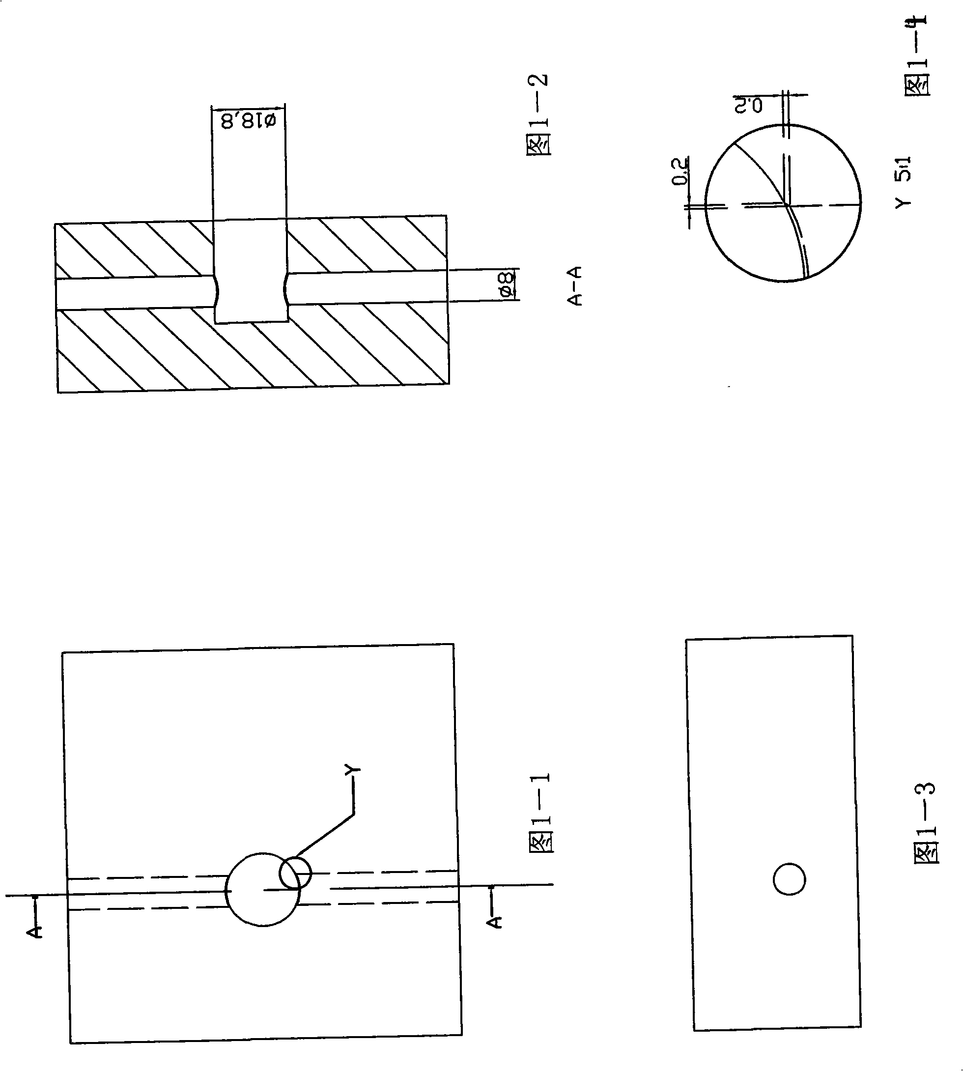
[0047] The present invention designs a tool with a special shape through proe three-dimensional software modeling, enters from hole B, takes a straight line and circular interpolation, and chamfers the intersecting line of the two holes by 0.2mm to ensure the removal of burrs. The following are φ8.0 and φ18. 8, the program of cross hole machining is as follows:

[0048] 04117

[0049] G90G00X4.0Y-0.6S7000M07M08

[0050] Z-23.26

[0051] G01X5.0X4.95F800

[0052] G03X5.08X5.03Y-0.12R1.5F800

[0053] G00X0Y-0.6

[0054] G00X-4.0Y0.6

[0055] G01X-4.95F800

[0056] G02X-5.08X-5.03Y0.12R1.5

[0057] G00Y0.6X0

[0058] X0Y0

[0059] Z32.0

[0060] M99

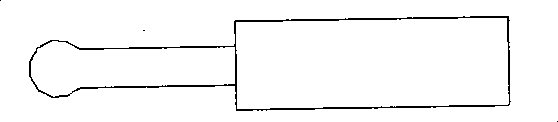
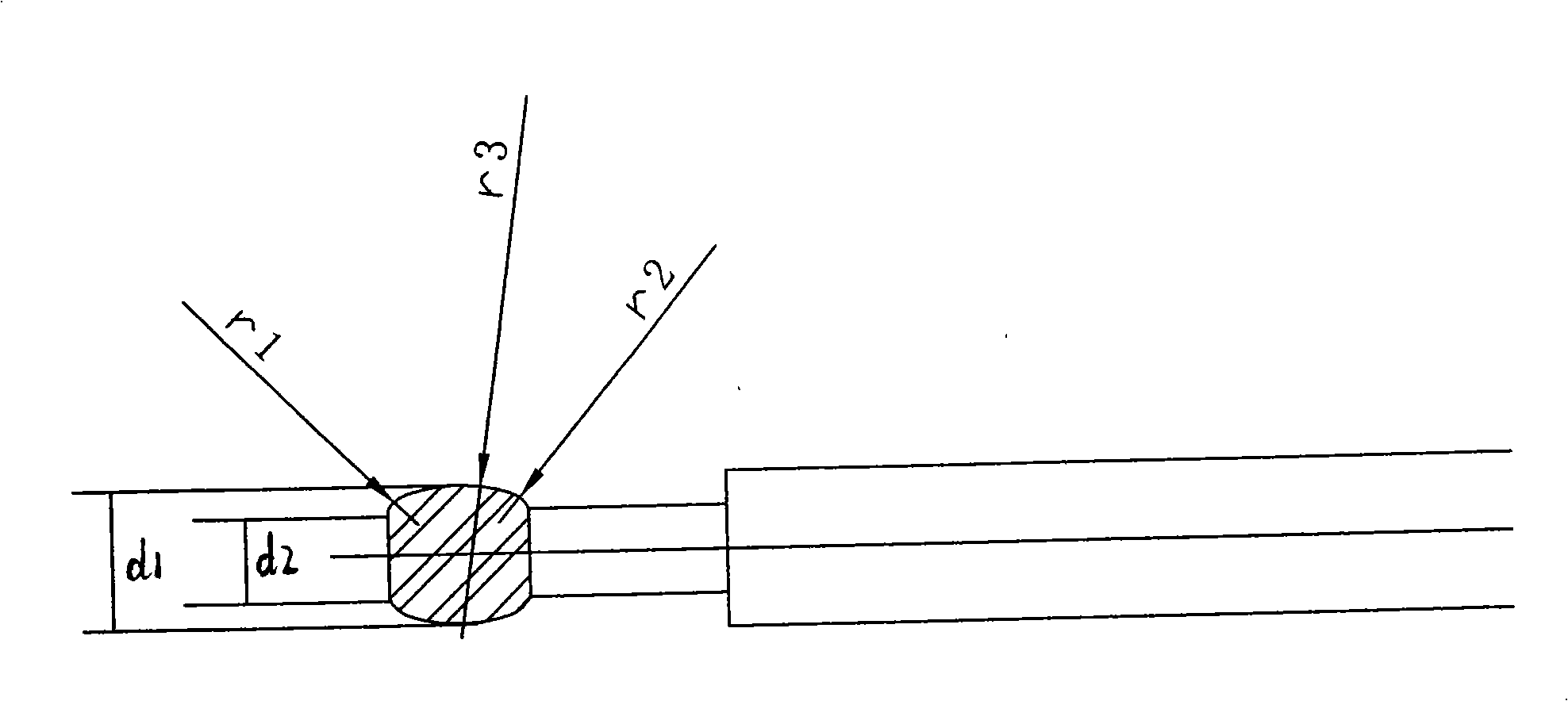
[0061] The tool shape of the linear interpolation used by the present invention and the coordinates of the written ...


PUM

PropertyMeasurementUnit
diameteraaaaaaaaaa
diameteraaaaaaaaaa
radiusaaaaaaaaaa

Abstract

The invention discloses a cutter for removing burrs of cross holes. The cutting edge of the cutter consists of a first circular arc, a second circular arc, and a third circular arc which are tangent to each other. The semidiameter of the first circular arc is 2.5 millimeters; the semidiameter of the second circular arc is 11.8 millimeters; and the semidiameter of the third circular arc is 2.5 millimeters. The invention further discloses a method for designing the cutter for removing the burrs of cross holes. The process period by adopting linear interpolation is significantly reduced compared with the process period by adopting the circular interpolation of linkage of three shafts.

Description

technical field [0001] The invention relates to the technology of hydraulic parts, in particular to a tool design method for deburring cross holes and the tool. Background technique [0002] Relevant hydraulic parts have particularly high requirements on cleanliness and burrs, and many hydraulic parts have criss-cross holes. During machining, flanging burrs are most likely to occur at the places where the holes intersect, and the burrs at the cross holes are cleaned by electrochemical or other methods. If the non-machining process removes the burr, the cost will be higher. If the part is processed on the CNC machine tool and the burr is removed by chamfering, the cost should be the lowest. [0003] Figure 1-1~Figure 1-4, introduce the intersection of hole A (diameter 18.8) and hole B (diameter 8.0), the common processing technology of hole A and hole B at home and abroad is to process hole A first and then process hole B Holes, because metal cutting will definitely produce ...

Claims


Application Information

Patent Timeline
Patent Type & Authority Applications(China)
IPC IPC(8): G05B19/4097B23D79/04
Inventor 方必余
Owner SHANGHAI REAL INDAL
Why Eureka
Try Eureka