Supercharge Your Innovation With Domain-Expert AI Agents!

Electric Connector

A technology of electrical connectors and contact parts, which is applied in the direction of connection, two-component connection devices, circuits, etc., can solve the problems of connectors that cannot be connected, small size, and inapplicable fool-proof structure, and achieve good anti-mis-insertion effect and structure simple effect

Active Publication Date: 2008-12-17
FOXCONN (KUNSHAN) COMPUTER CONNECTOR CO LTD +1
View PDF3 Cites 5 Cited by
  • Summary
  • Abstract
  • Description
  • Claims
  • Application Information

AI Technical Summary

Problems solved by technology

Chinese Patent No. ZL200520107383.9 discloses an anti-mis-insertion device. The anti-mis-insertion device is a metal sheet arranged in the housing cavity of the insulating body. It is stored in the storage cavity, and the non-matching butt connector (that is, the smaller plug connector) cannot be pushed away by the anti-mis-insertion device due to its small size, but is blocked by it and cannot fully enter the storage cavity, that is, the two connections device cannot be connected
However, the terminal module is only one type of the above-mentioned connector terminals, and the fool-proof structure is not suitable for other types of terminals, and the above-mentioned terminal module with the supporting part is relatively complicated, which is not conducive to mold development

Method used


Image

  • Electric Connector
  • Electric Connector
  • Electric Connector

Examples


Embodiment Construction

[0017] Figure 1 to Figure 4 is the first embodiment of the present invention, Figure 5 To Fig. 9 is the second embodiment of the present invention.

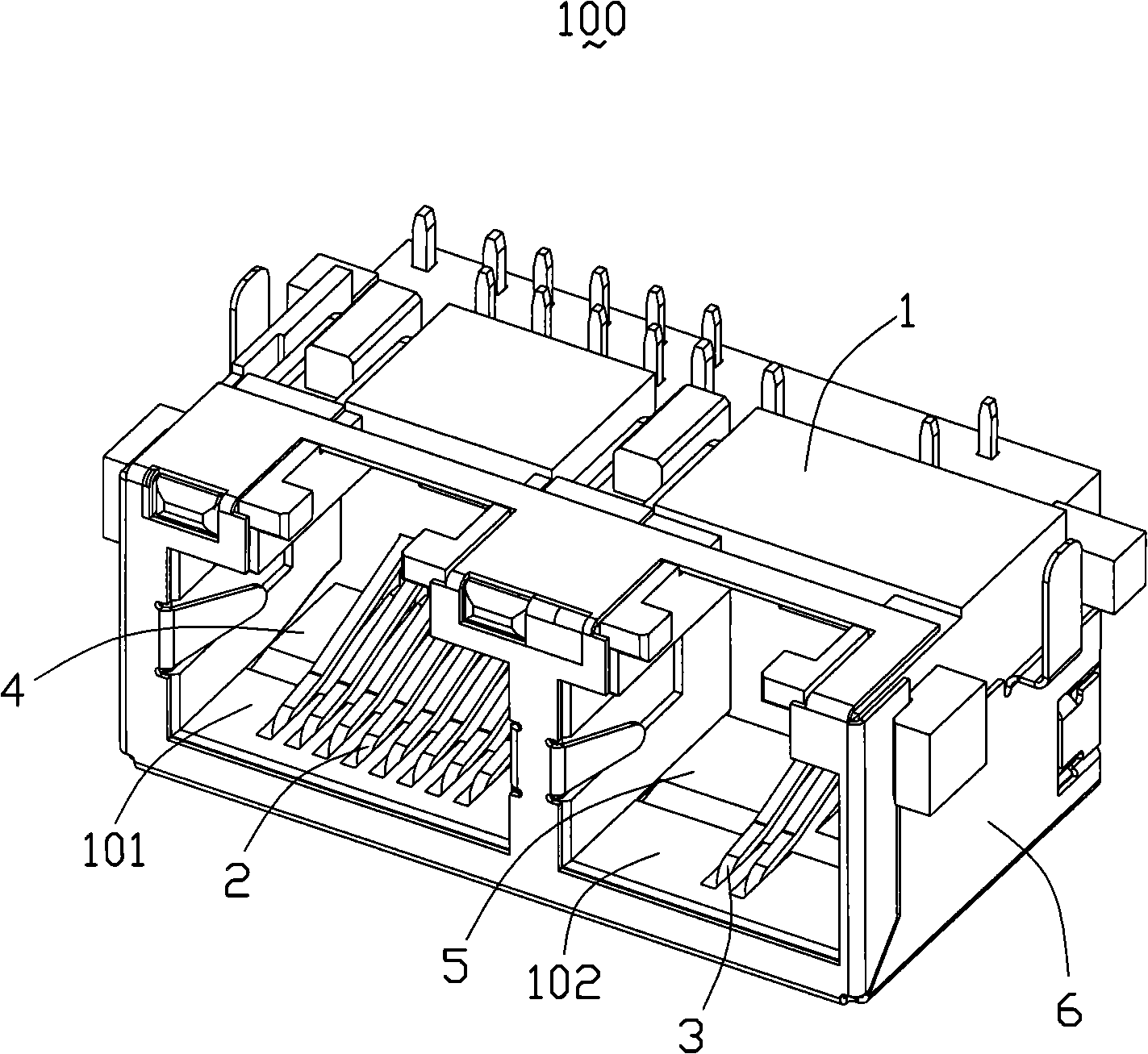
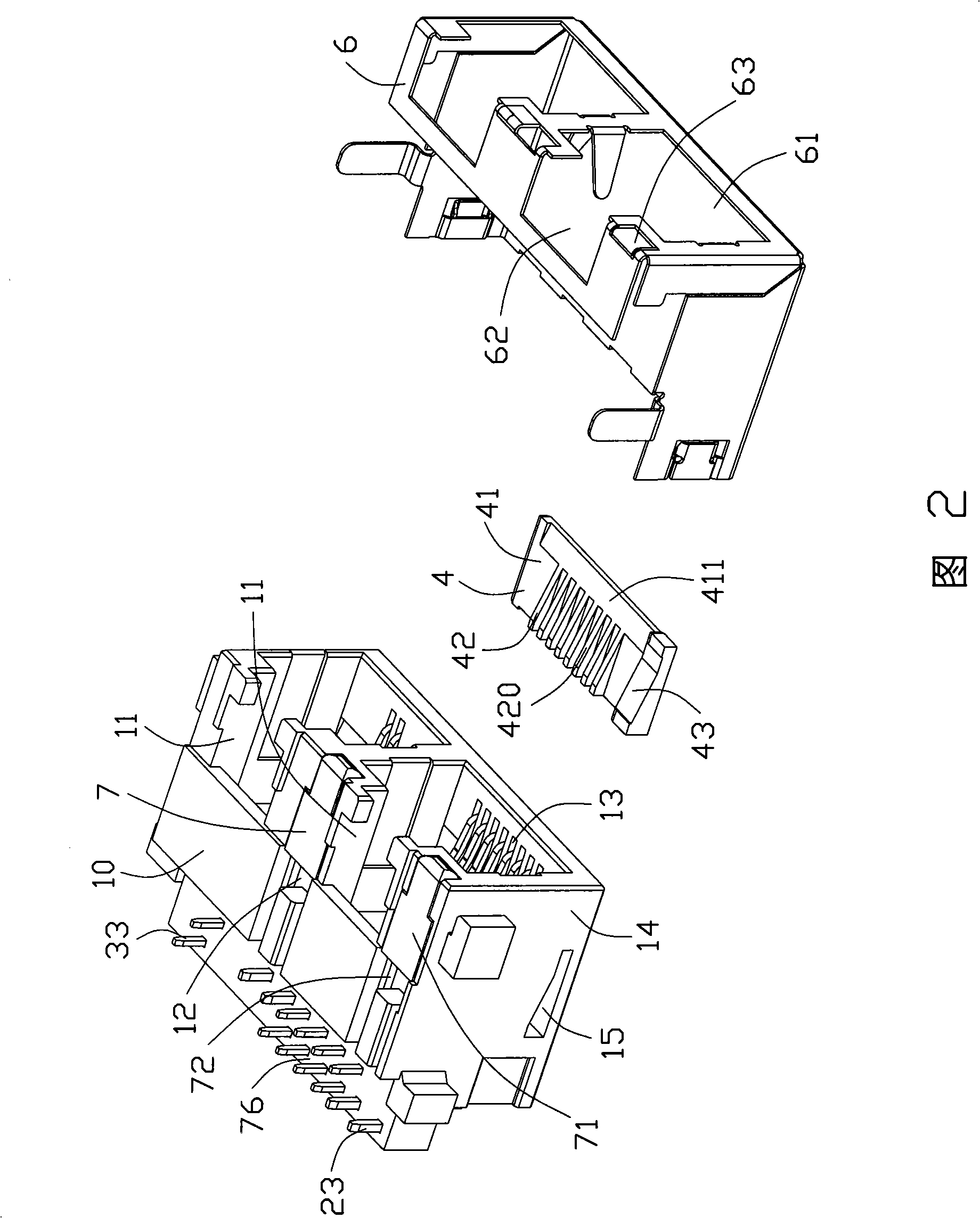
[0018] Please refer to figure 1 As shown, the first embodiment of the electrical connector of the present invention is a combined electrical connector 100 , which can be inserted into different mating connectors. The combined electrical connector mainly includes an insulating body 1 , conductive terminals 2 , 3 , limiting pieces 4 , 5 and a shielding case 6 .

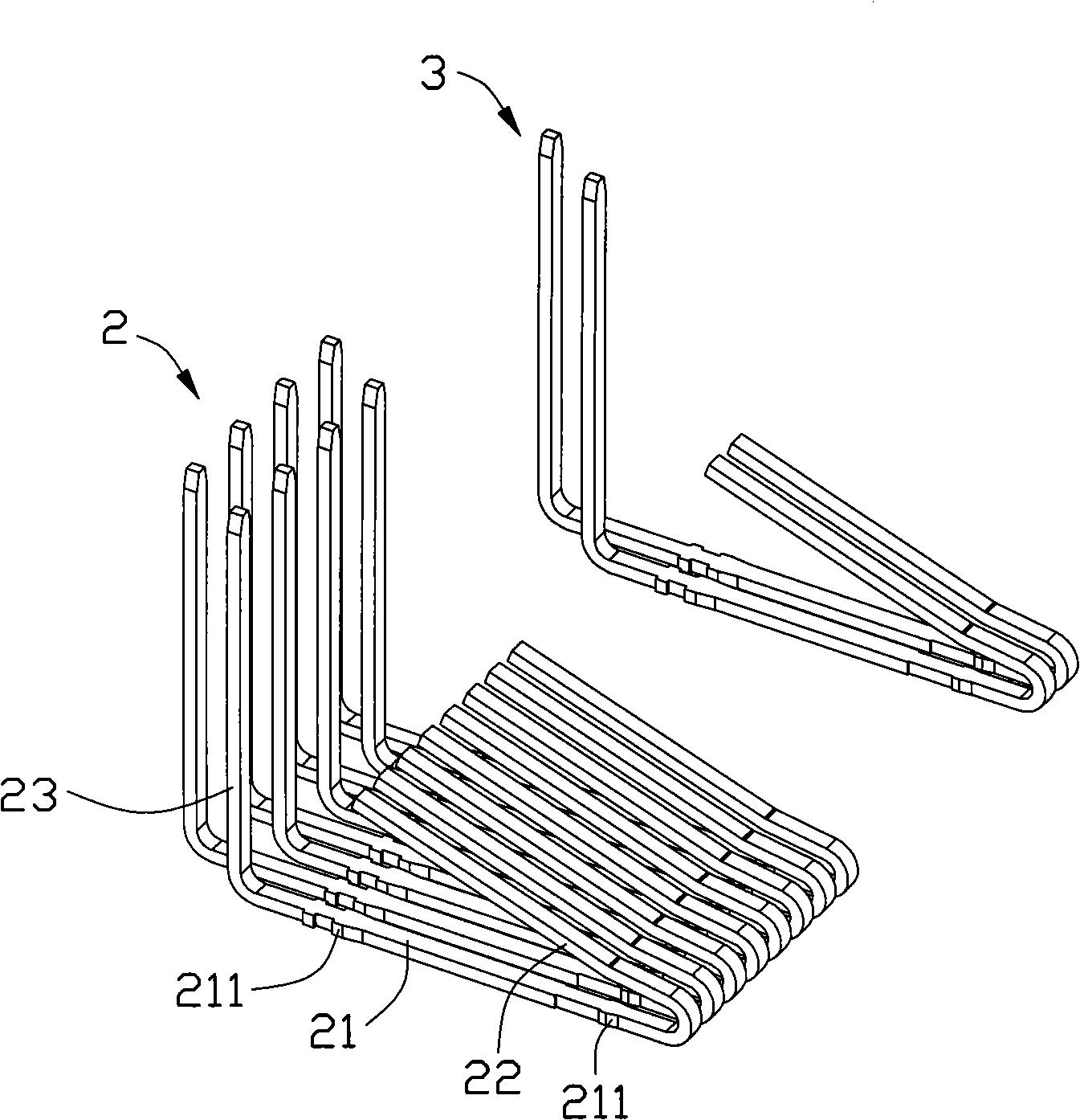
[0019] The insulating body 1 is provided with first and second receiving cavities 101 , 102 penetrating through the front end surface. Eight first terminals 2 are arranged in the first receiving cavity 101 , and two second terminals 3 are arranged in the second receiving cavity. The two accommodating cavities are arranged at intervals, and the first accommodating cavity 101 is larger than the second accommodating cavity 102 . As known to those in the industry, the fi...


PUM


Abstract

The invention discloses an electrical connector, which comprises an insulating body (1), a conducting terminal (2) and a limiting piece (4), wherein the insulating body is provided with an accommodation cavity (101) which passes through a wall surface of the insulating body; the terminal comprises a contact part (22) extending into the accommodation cavity; the limiting piece (4) is inserted at the lower part of the contact part (22) of the contact part (22) of the terminal; an inclined supporting surface (420) arranged on the limiting piece can prevent the contact part from being excessively deviated. The limiting piece singly designed through the electrical connector has the advantages of relative simple structure, and performs a good function of preventing misplug.

Description

【Technical field】 [0001] The invention relates to an electrical connector, in particular to an electrical connector which can prevent misplugging. 【Background technique】 [0002] In order to prevent two non-matching connectors from being docked, the electrical connector needs to be equipped with an anti-mis-insertion device. Chinese Patent No. ZL200520107383.9 discloses an anti-mis-insertion device. The anti-mis-insertion device is a metal sheet arranged in the housing cavity of the insulating body. It is stored in the storage cavity, and the non-matching butt connector (that is, the smaller plug connector) cannot be pushed away by the anti-mis-insertion device due to its small size, but is blocked by it and cannot fully enter the storage cavity, that is, the two connections device cannot be connected. However, the anti-mis-insertion device not only increases the number of components, but also occupies a small space of the electrical connector, which does not conform to th...

Claims


Application Information

Patent Timeline
Patent Type & Authority Applications(China)
IPC IPC(8): H01R13/64
CPCH01R13/26H01R24/64
Inventor 王宁
Owner FOXCONN (KUNSHAN) COMPUTER CONNECTOR CO LTD
Features
  • R&D
  • Intellectual Property
  • Life Sciences
  • Materials
  • Tech Scout
  • Unparalleled Data Quality
  • Higher Quality Content
  • 60% Fewer Hallucinations
Learn More