Hole-punching and switching mechanism of mould

A switching mechanism and punching technology, which is applied in the field of punching die devices, can solve the problems of high development costs

Inactive Publication Date: 2008-12-24
CHONGQING CHANGAN AUTOMOBILE CO LTD
View PDF0 Cites 24 Cited by
  • Summary
  • Abstract
  • Description
  • Claims
  • Application Information

AI Technical Summary

Problems solved by technology

Usually, the car roof in these two states needs to be punched out on two molds, so there is a problem of high development cost

Method used


Image

  • Hole-punching and switching mechanism of mould
  • Hole-punching and switching mechanism of mould
  • Hole-punching and switching mechanism of mould

Examples


Embodiment Construction

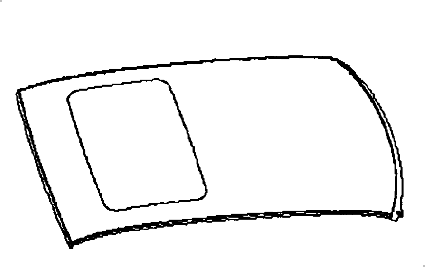
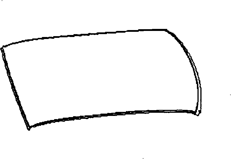
[0011] Taking the production of automobile roof as an example below, the present invention will be described in further detail in conjunction with the accompanying drawings and specific embodiments.

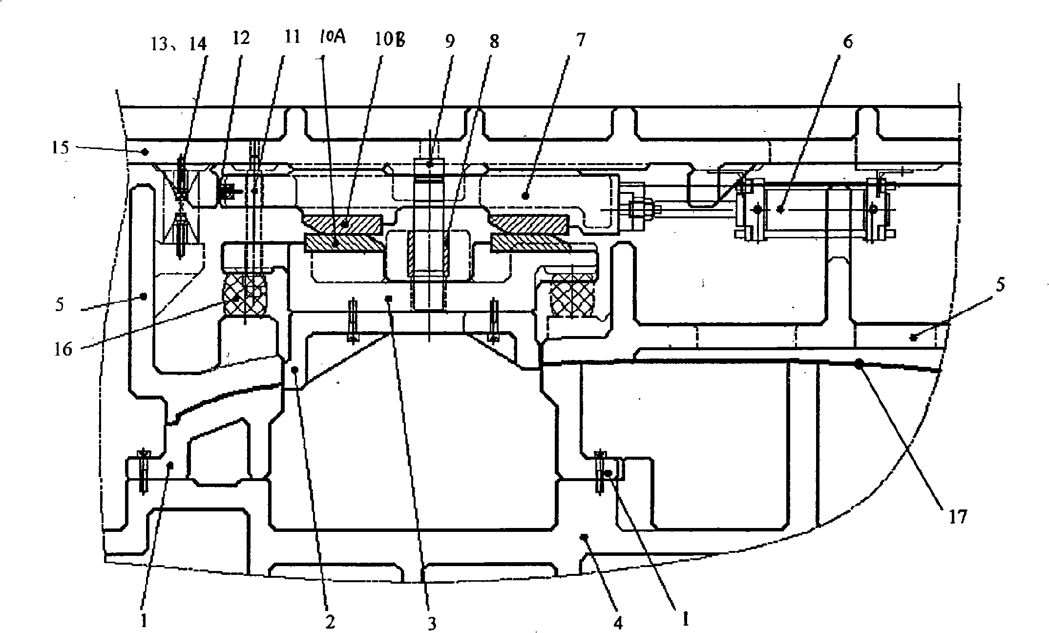
[0012] Such as image 3 As shown, the switching mechanism consists of punching die 1, punching punch 2, punch mounting seat 3, lower die base 4, presser 5, air cylinder 6, driver 7, guide sleeve 8, guide post 9, wedge Sliding plate, safety screw 11, polyurethane buffer pad 12, spring guide pin 13, spring 14, upper mold base 15 and polyurethane spring 16 etc. are formed. The punching die 1 is fixed on the lower die base 4, the punching punch 2 is fixed on the punch mounting base 3, the edge of the punch mounting base 3 is supported on the presser 5 by the polyurethane spring 16, and the punch mounting base 3 The upper part of the upper part is fixed with a wedge slide 10A; the air cylinder 6 is fixed on the upper mold base 15, and its movable end is connected with the driver 7, w...


PUM


Abstract

The invention discloses a punching switching mechanism of a die, which consists of a piercing female die, a piercing male die, a male die installation seat, a lower die holder, an eccentric swage, an air cylinder, a drive, inclined wedge skateboards and an upper die holder, etc. The piercing female die is fixed on the lower die holder; the piercing male die is fixed on the male die installation seat; a lower inclined wedge skateboard is fixed at the upper part of the male die installation seat; the air cylinder is fixed on the upper die holder, wherein, the free end of the air cylinder is connected with the drive to pull the drive to move horizontally; an upper inclined wedge skateboard is fixed below the drive to work with the lower inclined wedge skateboard fixed at the upper part of the male die installation seat. The mechanism adopts the air cylinder as the power source to switch the horizontal movement to vertical movement via the inclined wedge skateboards, and to protrude the piercing male die out of the eccentric swage for punching or to withdraw the piercing male die into the eccentric swage to stop punching, thus achieving punching switching. The mechanism has the advantages of high accuracy, stable and reliable movement and easy manufacturing.

Description

technical field [0001] The invention relates to a punching die device, in particular to a punching switching mechanism in the die. Background technique [0002] In the stamping of some products using molds, different models of the same product may have local changes. For example, one type of product needs to open a hole in a certain position, while another type does not need to open a hole. For example, in the production of the top cover of the car, such as figure 1 and figure 2 As shown, the roof of the car generally has two states: the state with sunroof ( figure 1 ) and no sunroof state ( figure 2 ). Usually, these two states of the car roof need to be punched out on two molds, so there is a problem of high development cost. Contents of the invention [0003] The technical problem to be solved by the present invention is to provide a punching switching mechanism in the mold, which can be applied to products of the same shape that need or do not need holes at the ...

Claims


Application Information

Patent Timeline
Patent Type & Authority Applications(China)
IPC IPC(8): B21D37/02B21D37/10B21D28/24
Inventor 刘春达陈立军
Owner CHONGQING CHANGAN AUTOMOBILE CO LTD
Why Eureka
Try Eureka