Method for calculating and installing high-speed rail electrification catenary wrist-arm

A technology for high-speed railways and installation methods, which is applied in computing, electrical digital data processing, and special data processing applications, and can solve problems such as complex positioning and large line time occupation

Inactive Publication Date: 2008-12-24
CHINA RAILWAY 11TH BUREAU GRP +2
View PDF0 Cites 19 Cited by
  • Summary
  • Abstract
  • Description
  • Claims
  • Application Information

AI Technical Summary

Problems solved by technology

However, the positioning of the flat and inclined arms is complicated during the in

Method used


Image

  • Method for calculating and installing high-speed rail electrification catenary wrist-arm
  • Method for calculating and installing high-speed rail electrification catenary wrist-arm
  • Method for calculating and installing high-speed rail electrification catenary wrist-arm

Examples


Embodiment 1

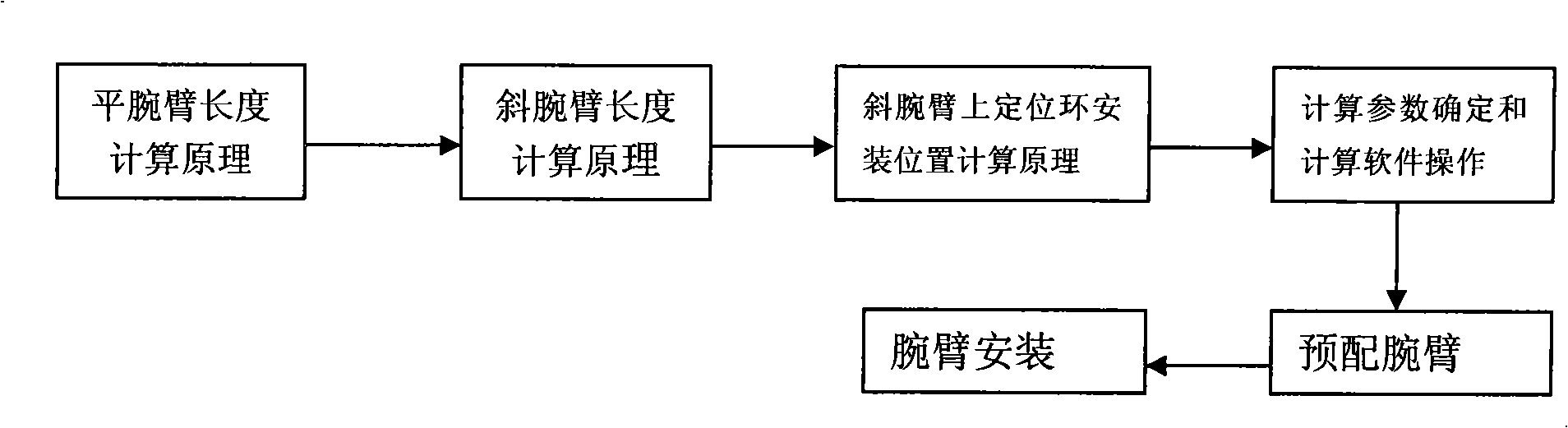
[0085] The present invention high-speed railway electrification catenary arm calculation and installation method, such as figure 1 As shown, it includes: calculation of the length of flat wrist arm 1, calculation of the length of the positioning tube of inclined wrist arm 2, calculation of the installation position of positioning ring 5 on the inclined wrist arm, pre-configuration of the wrist arm, and installation of the wrist arm.

[0086] The calculation of the length of the flat wrist 1 includes: the calculation of the length of the flat wrist 1 without raising and the calculation of the length of the flat wrist 1 with raising.

[0087] For the calculation of the flat wrist-arm length without raising, the following formula is used:

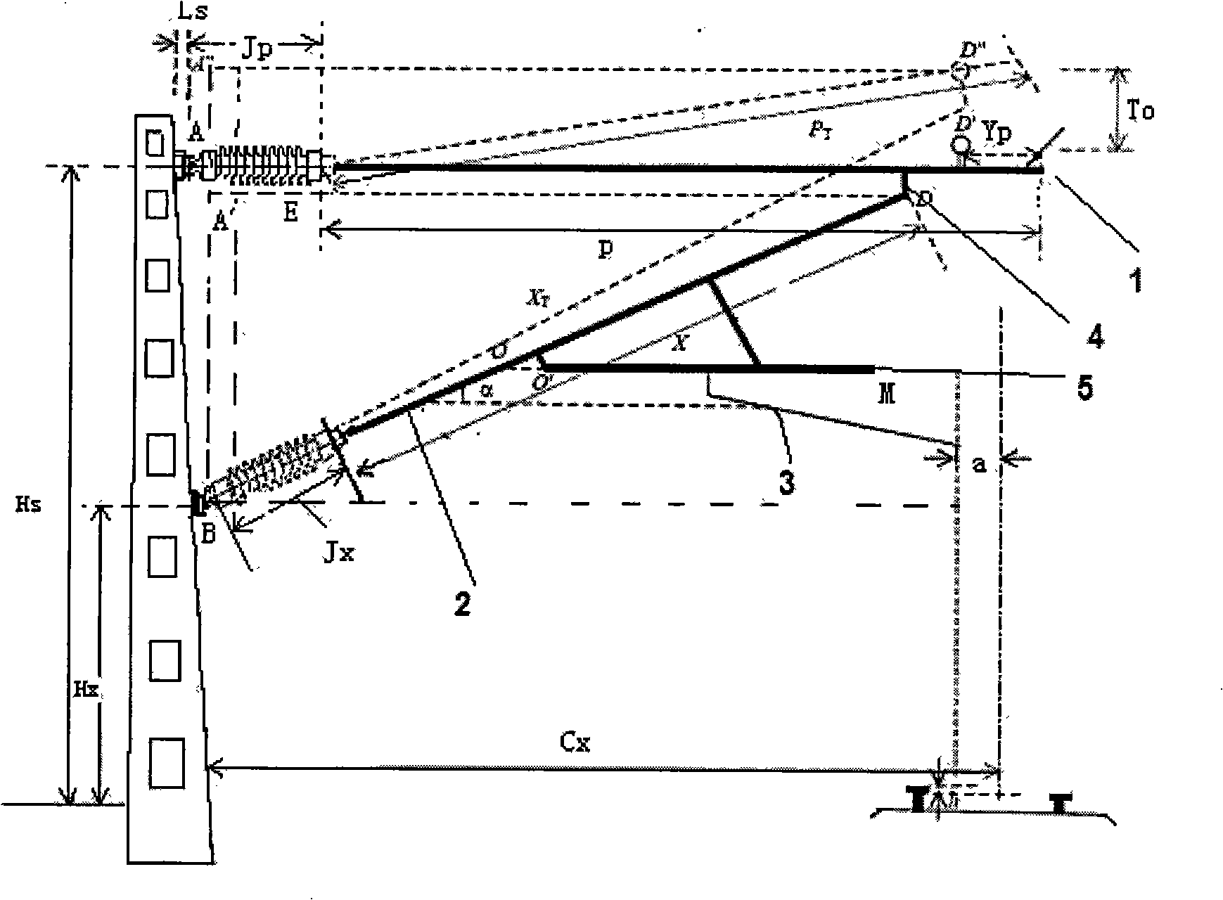
[0088] P=δ·H s / 1000+C x -h·G c / G k -a+Q z -J p -L s +Y p

[0089] The stated wrist-arm length with elevation, calculated using the following formula

[0090] P T = ...

Embodiment 2

[0144] The present invention high-speed railway electrification catenary arm calculation and installation method, such as figure 1 As shown, it includes: calculation of the length of flat wrist arm 1, calculation of the length of the positioning tube of inclined wrist arm 2, calculation of the installation position of positioning ring 5 on the inclined wrist arm, pre-configuration of the wrist arm, and installation of the wrist arm.

[0145] When the wrist arm is not raised, the calculation of the length of the flat wrist arm 1 adopts the following formula:

[0146] P=δ·H s / 1000+C x -h·G c / G k -a+Q z -J p -L s +Y p

[0147] The calculation of the length of the oblique arm 2 adopts the following formula:

[0148] X = L a 2 + L b 2 - Jx

[0149] Among them, La=δ·H x / 1000+C x -h·G c ...

Embodiment 3

[0165] The present invention high-speed railway electrification catenary arm calculation and installation method, such as figure 1 As shown, it includes: calculation of the length of flat wrist arm 1, calculation of the length of the positioning tube of inclined wrist arm 2, calculation of the installation position of positioning ring 5 on the inclined wrist arm, pre-configuration of the wrist arm, and installation of the wrist arm.

[0166] When the wrist arm is raised, the calculation of the length of the flat wrist arm 1 adopts the following formula:

[0167] P T = T G 2 + ( δ · H s / 1000 + ...


PUM


Abstract

The present invention relates to a cantilever calculation and installation method of electrified contact line of high-speed railway, which comprises calculating the length of the flat cantilever, the length of the inclined cantilever pipe, the position of the positioning ring on the inclined cantilever and the cantilevers, preparing the cantilevers, and installing the cantilevers. The method belongs to the electromechanical field of rail traffic, in particular to the construction method of installing the flat cantilever and the inclined cantilever on the contact line of the high-speed railway. The method solves the problem that a large amount of line time is consumed in the construction because of the complex positioning of the flat cantilever and the inclined cantilever in the installation process. The construction method has high efficiency, makes full use of the time of non-closed points, accurately calculates and prepares the cantilevers, reduces a large amount of on-site adjusting time and railway holding time, and greatly improves the economic benefits.

Description

technical field [0001] The invention relates to a calculation and installation method for a high-speed railway electrified catenary arm, which belongs to the field of railway traffic electromechanics, in particular to a construction method for installing a flat and inclined arm on a high-speed railway catenary. Background technique [0002] At present, the structural stability of the horizontal tie-rod support and positioning device for the electrified railway catenary is poor, and it can no longer meet the needs of high-speed train operation. The design of the catenary arm structure of high-speed electrified railway adopts the rigid support structure with flat and oblique arm positioning, which changes the stress state of the catenary cable and eliminates the defect that the catenary shakes under the adjustment operation state. However, the positioning of flat and inclined arms is complicated during installation, and a large amount of line time will be taken up during const...

Claims


Application Information

Patent Timeline
IPC IPC(8): B60M1/20G06F19/00
Inventor 谢文艺夏谦云周梅芝
Owner CHINA RAILWAY 11TH BUREAU GRP
Why Eureka
Try Eureka