
Whirler crane

A crane and slewing technology, applied in the directions of crane, transportation and packaging, can solve the problem of inconvenient use of the crane

Inactive Publication Date: 2008-12-24
BAOSONG IND DEV SHANGHAI
View PDF0 Cites 6 Cited by
  • Summary
  • Abstract
  • Description
  • Claims
  • Application Information

AI Technical Summary

Problems solved by technology

If the space structure is relatively complex and there are many obstacles (such as columns), the above cranes are not convenient to use.

Method used


Image

  • Whirler crane
  • Whirler crane
  • Whirler crane

Examples


Embodiment Construction

[0026] The preferred embodiments of the present invention are given below in conjunction with the accompanying drawings to describe the technical solution of the present invention in detail.

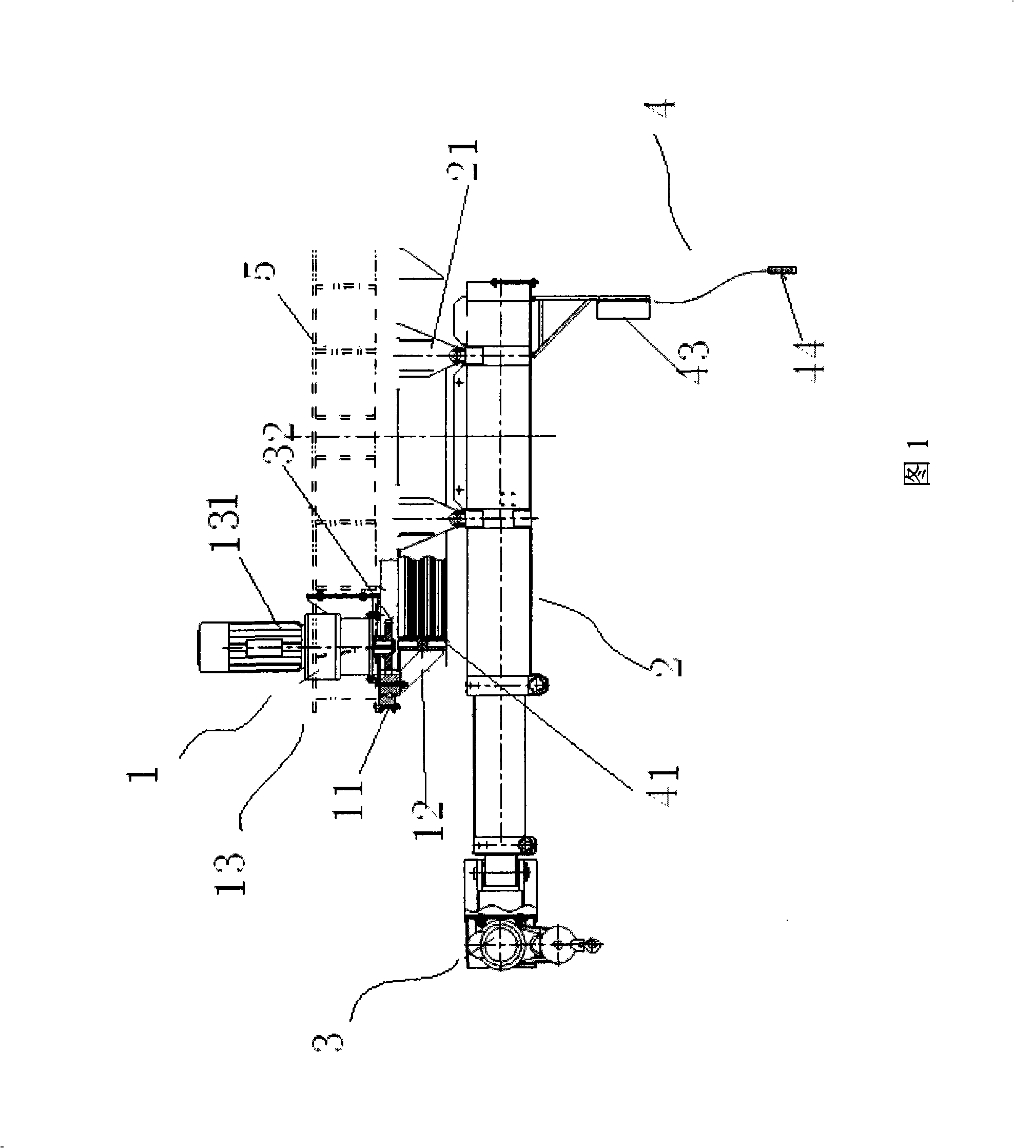
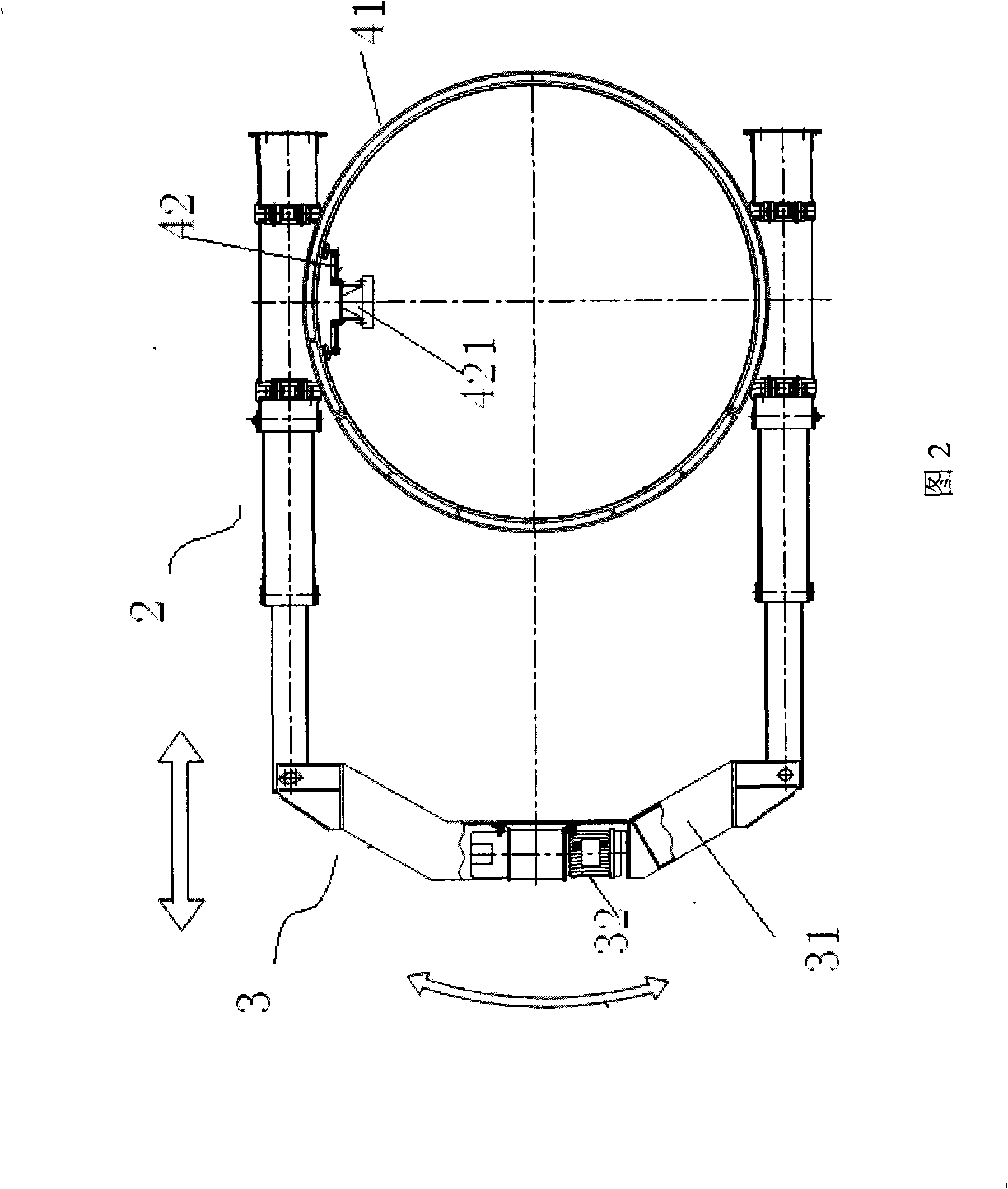
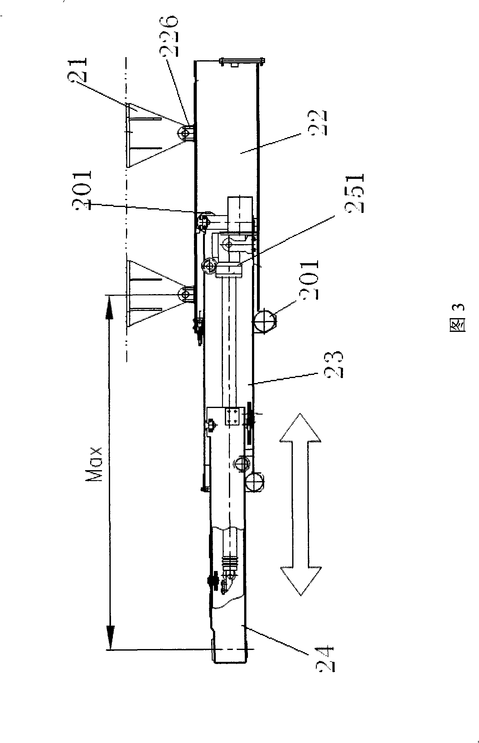
[0027] A slewing crane mainly includes: a slewing mechanism 1 , a telescoping system 2 , a lifting system 3 , and a conductive and control system 4 .

[0028] Wherein, the rotary device 1 mainly includes a rotary support 11 , a turntable 12 and a rotary drive device 13 . Wherein the slewing support 11 includes an inner ring and an outer ring, which are installed horizontally, the outer ring is connected with the upper fixed steel frame of the factory building through bolts, and the inner ring is connected with the rotating disk 12 . The rotary driving device 13 is composed of a cycloidal pinwheel deceleration motor 131 and a driving gear 132. The driving device 13 is fixedly installed on the fixed steel frame of the workshop, and the gear 132 is mounted on the output shaft of the deceler...


PUM


Abstract

The present invention discloses a slewer, comprising a rotary support which comprises an outer ring fixed to a fixed steel frame of a factory building, a inner ring arranged inside the outer ring, and a rotary driving device with an output shaft in gear connection with the inner ring; a telescopic system which comprises one or more basic arm that is fixed to the inner ring through two or more basic arm supports respectively and two or more telescopic arms that are respectively connected with the basic arm; a lifting device which comprises a lifting beam and a lifting mechanism arranged on the beam; an electric conduction and control system which comprises an electric conduction slip ring that is electrically connected with the lifting mechanism, the rotary driving device and a control case. Since the crane has two functions of gyration and telescopic, the crane can be used in the environment where the space structure is complex and impediments are excessive. Furthermore, the telescopic arm adopts electric drive so that the crane has the advantages of no noise and no pollution, etc.

Description

technical field [0001] The invention relates to a light crane, in particular to a slewing crane. Background technique [0002] Commonly seen slewing cranes such as car and tire cranes, construction tower cranes or double-girder bridge and gantry cranes with slewing trolleys on them. If the space structure is relatively complex and there are many obstacles (such as columns), the above cranes are inconvenient to use. [0003] And the existing telescopic arm device generally adopts driving devices such as hydraulic cylinder, leading screw nut, rack and pinion, cylinder. Contents of the invention [0004] The object of the present invention is to provide a slewing crane used in an environment with complex spatial structure and many obstacles. [0005] The purpose of the present invention is achieved through the following technical solutions: [0006] A slewing crane comprising: [0007] A slewing bearing, which includes an outer ring fixed on the fixed steel frame of the f...

Claims


Application Information

Patent Timeline
IPC IPC(8): B66C25/00
Inventor 黄冠焯
Owner BAOSONG IND DEV SHANGHAI
Learn More