

Inflating mould for concrete filling
A technology for pneumatic tires and tire molds, which is applied in the field preparation and construction of mold shells/templates/work frames, building components, etc., can solve the problems of occupying transportation space, complicated production molds, inconvenient handling, etc. The effect of enhancing strength, enhancing strength and toughness
- Summary
- Abstract
- Description
- Claims
- Application Information
AI Technical Summary
Problems solved by technology
Method used
Image

Examples
Embodiment Construction
[0037] The present invention will be further described below in conjunction with drawings and embodiments.
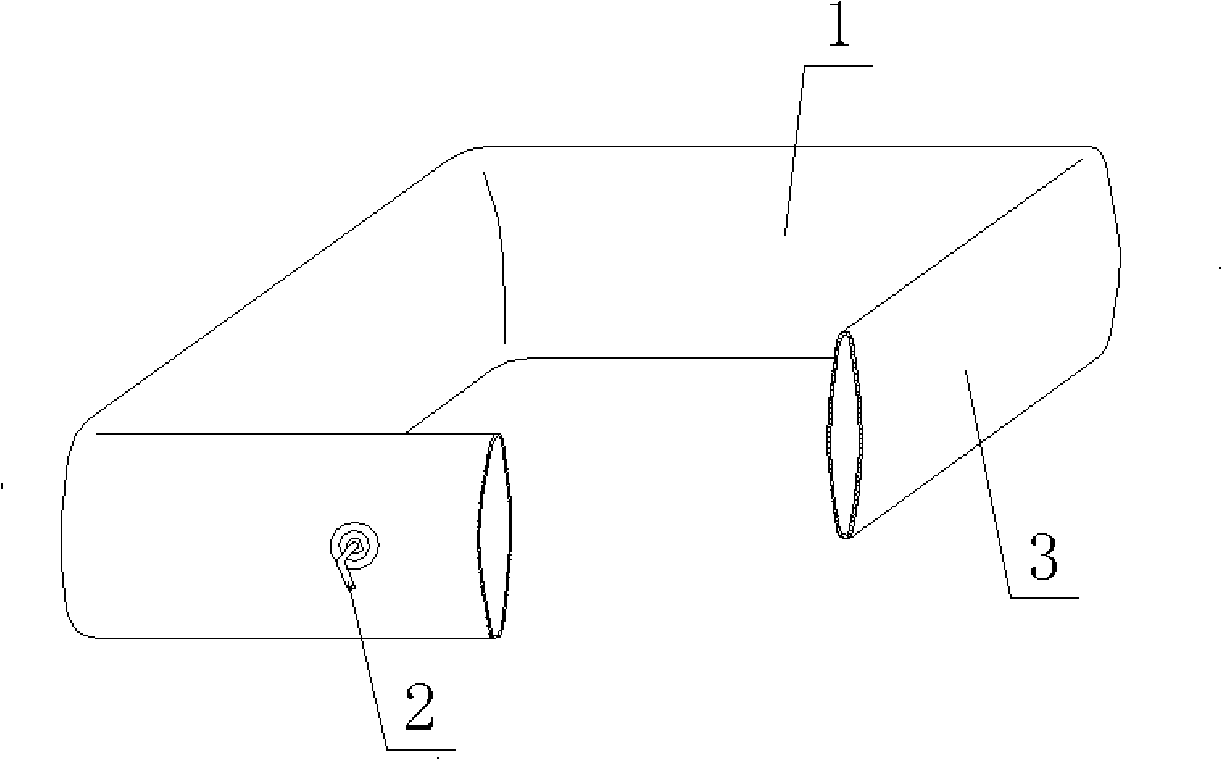
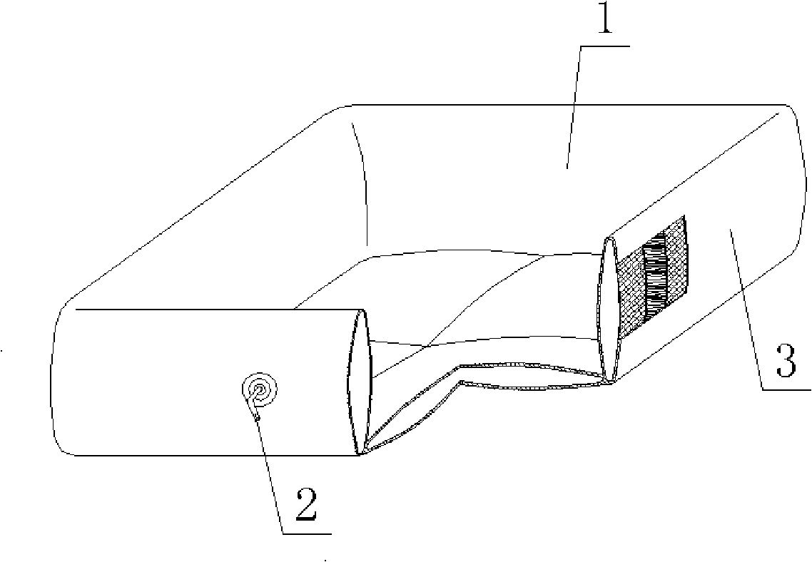
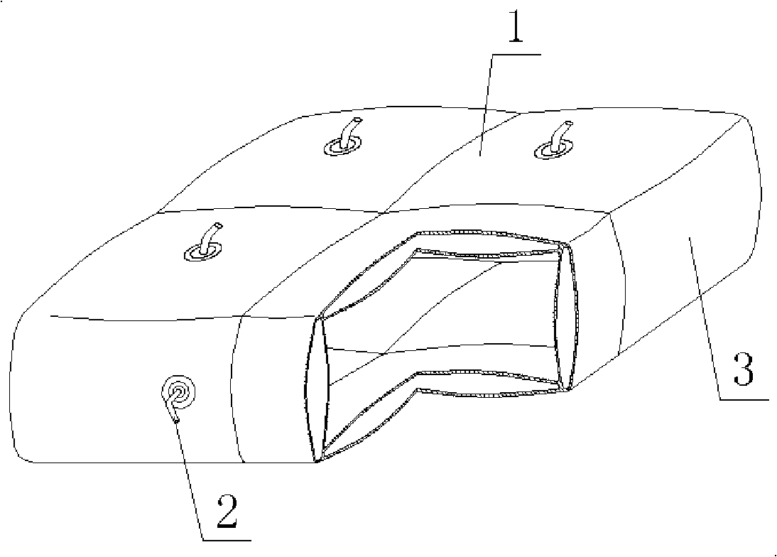
[0038] As shown in the accompanying drawings, the present invention includes a soft mold wall 1 and an inflatable insert 2. The soft mold wall 1 is closed to form a tire mold 3. It is characterized in that the inflatable insert 2 is an inflatable nozzle that can be closed by itself when the insert is pulled out. Set with inflation nozzle. figure 1 It is a structural schematic diagram of Embodiment 1 of the present invention. In each accompanying drawing, 1 is a soft mold wall, 2 is an inflatable insert, and 3 is a tire mold. In each accompanying drawing, those with the same number have the same description. Such as figure 1 , 2 , 3, including a soft mold wall 1, an inflatable insert 2, the soft mold wall 1 is closed to form a tire mold 3, which is characterized in that the inflatable insert 2 is an inflatable nozzle that can be closed by itself when the insert is dra...
PUM
 Abstract
Description
Claims
Application Information