Wireless power supply system and method

A wireless power supply and wireless communication technology, applied in electromagnetic wave systems, circuit devices, electrical components, etc., can solve the problems of oversized receiving devices, gaps in transmission energy efficiency, difficulties, etc., to improve energy transmission efficiency, realize anti-theft and anti-theft problems. The effect of leakage and accurate transmission

Active Publication Date: 2008-12-24
SHENZHEN UNIV
View PDF0 Cites 31 Cited by
  • Summary
  • Abstract
  • Description
  • Claims
  • Application Information

AI Technical Summary

Problems solved by technology

As an experimental scheme, its disadvantage is that its equipment is only a simple fixture and cannot dynamically adjust various parameters. It is very difficult to achieve precise tuning for a more complex nonlinear coupling system, or even Impossible; the size of the receiving device is too large and inconvenient to use; the coaxial control requirements of the coupling coil are quite demanding; the transmission energy efficiency is also far from the theoretical calculation value of 80% to 90%.
In addition, there are some contact-type wireless power supply desktops, wireless chargers, etc., but these products belong to the ultra-macro distance system, that is, the power supply and load must be placed together in a very close distance, and the purpose of short-distance wireless power supply cannot be achieved.

Method used


Image

  • Wireless power supply system and method
  • Wireless power supply system and method
  • Wireless power supply system and method

Examples


Embodiment Construction

[0038] The features and advantages of the present invention will be described in detail through embodiments in conjunction with the drawings.

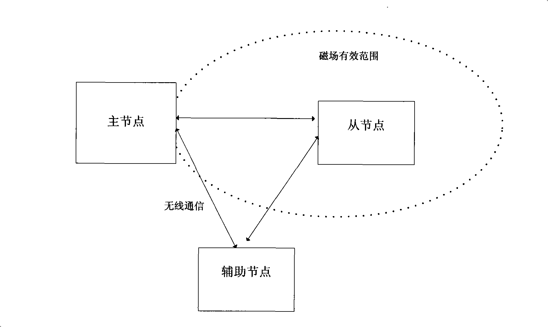
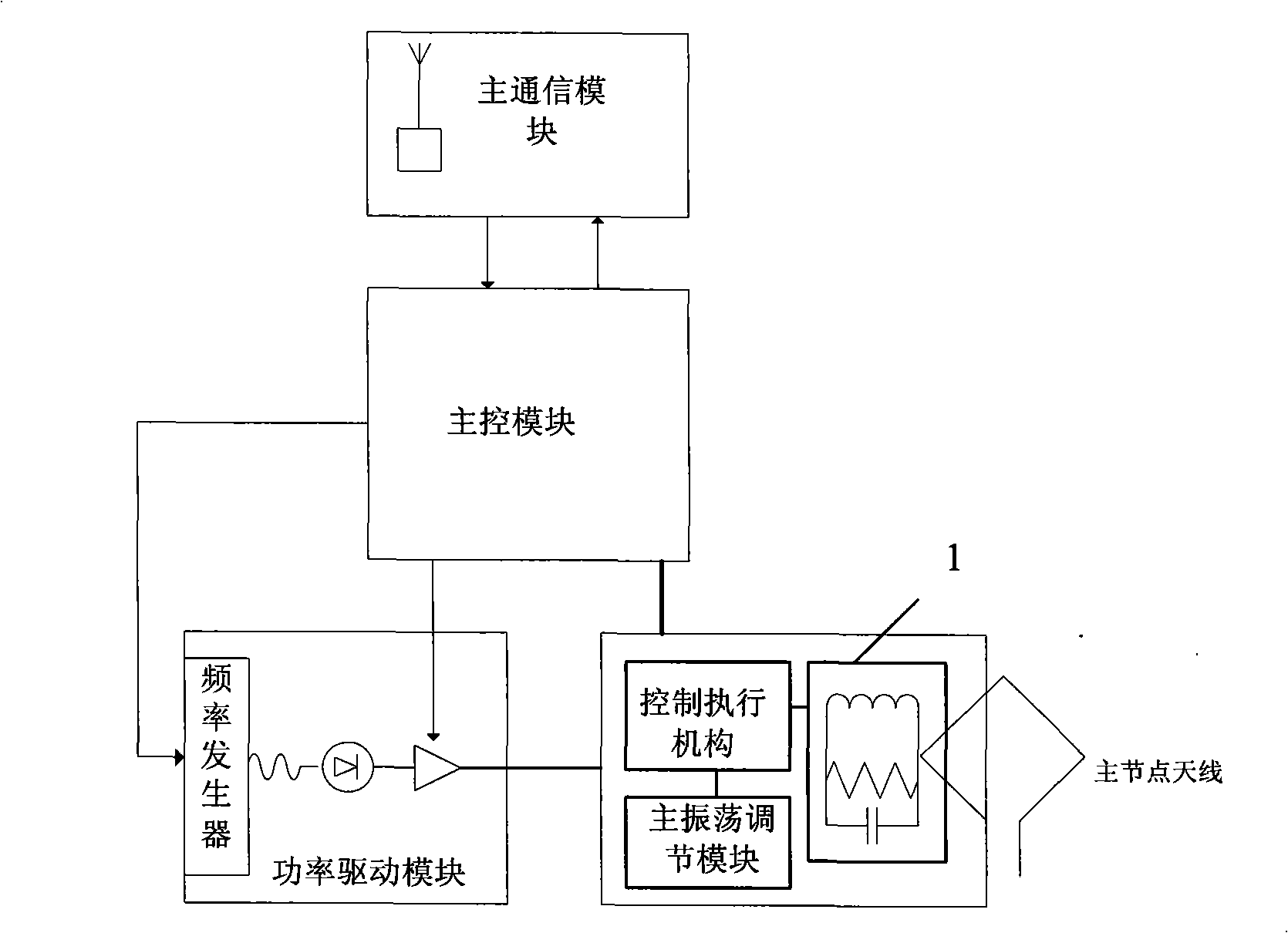
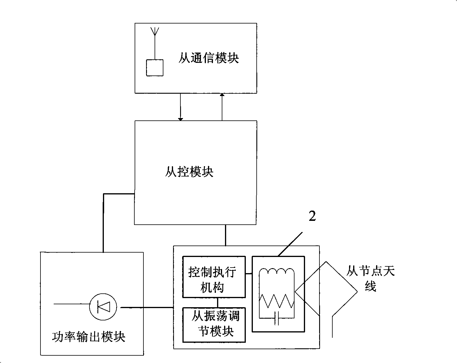
[0039] Please refer to figure 1 , The wireless power supply system includes a master node (energy supply source end), a slave node (energy supply target end) and an auxiliary node. The master node, as the energy supplier, converts AC electrical energy into electromagnetic field energy, and transmits energy to the outside through electromagnetic oscillation. The slave node acts as the energy requester. The slave node receives the electromagnetic field energy transmitted from the master node, and converts it into electromagnetic resonance. Electric energy, and output to the load. The coordinated work between the master node and the slave node is carried out through wireless communication. The auxiliary node also performs wireless communication with the master node and the slave node, and is used to provide useful information for determining...


PUM


Abstract

The invention discloses a wireless power supply system which comprises at least one energy-supply host node and at least one energy-consumption slave node. The host node comprises a host node antenna, a main control module, a main resonance loop, a main oscillation regulation module, a power drive module and a main communication module. The slave node comprises a slave node antenna, a secondary control module, a secondary resonance loop, a secondary oscillation regulation module, a power output module and a secondary communication module. The system further comprises at least an auxiliary node on the premise that the power supply system comprises only one host node and one slave node. The auxiliary node at least comprises a positioning communication module used for providing the host node with the information for positioning the slave node. The host node calculates the optimal control parameter according to the request and controls the operation of the host node and the slave node according to the obtained parameter, thereby realizing the efficiency optimization on the premise that the energy transfer meets the requirements. The invention also discloses a wireless power supply method. The method can control the resonance state of the coupled electromagnetic resonance between the host node and the slave node, thereby realizing the short-distance high-efficiency energy transfer.

Description

【Technical Field】 [0001] The invention relates to wireless power supply technology, in particular to a wireless power supply system and a wireless power supply method. 【Background technique】 [0002] With the development of science and technology, the freedom of people's activities has greatly increased. The emergence of smart terminals such as mobile phones has enabled people to seamlessly access the information society. However, wireless technology has remained in the information field for a long time, and its energy characteristics have not been as expected. development of. Therefore, the equipment we use must be equipped with a power cord or a battery. The idea of ​​wireless power supply has been around for a long time, but it is well known that electromagnetic waves radiate energy in all directions during the process of transmitting energy, which makes the power supply efficiency extremely low. In 2007, researchers at the Massachusetts Institute of Technology adopted a reson...

Claims


Application Information

Patent Timeline
Patent Type & Authority Applications(China)
IPC IPC(8): H02J17/00H02J50/12
Inventor 秦斌
Owner SHENZHEN UNIV
Why Eureka
Try Eureka