
Earphone microphone capable of adjusting clamping force

A clamping force, adjustable technology, applied in the direction of earpiece/earphone accessories, microphone mouth/microphone accessories, etc., to achieve the effect of convenient use, simple structure and comfortable wearing

Inactive Publication Date: 2011-07-27
NINGBO EXCEL ELECTRONICS
View PDF16 Cites 2 Cited by
  • Summary
  • Abstract
  • Description
  • Claims
  • Application Information

AI Technical Summary

Problems solved by technology

[0002] Headphones usually use the connecting rod between the left and right earphones, such as: the elastic force of plastic or metal strips as the clamping force of the earphones. To clamp the ear, in order to make the earphone can be reliably clamped, the production or design unit often uses a larger clamping force than the actual need to clamp. Due to the excessive clamping force, the force cannot be effectively adjusted, so When using the earphones for a long time, it will cause ear pain and headache due to excessive clamping force, which not only affects the health of the body, but also sharply reduces the pleasant mood

Method used


Image

  • Earphone microphone capable of adjusting clamping force
  • Earphone microphone capable of adjusting clamping force
  • Earphone microphone capable of adjusting clamping force

Examples


Embodiment

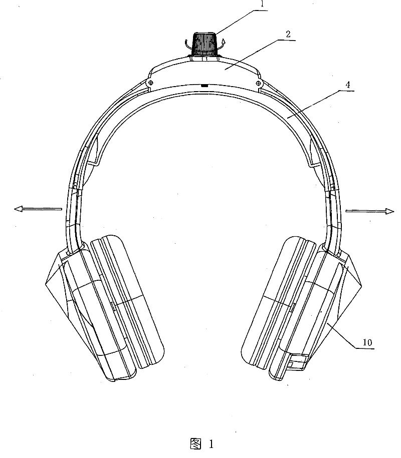
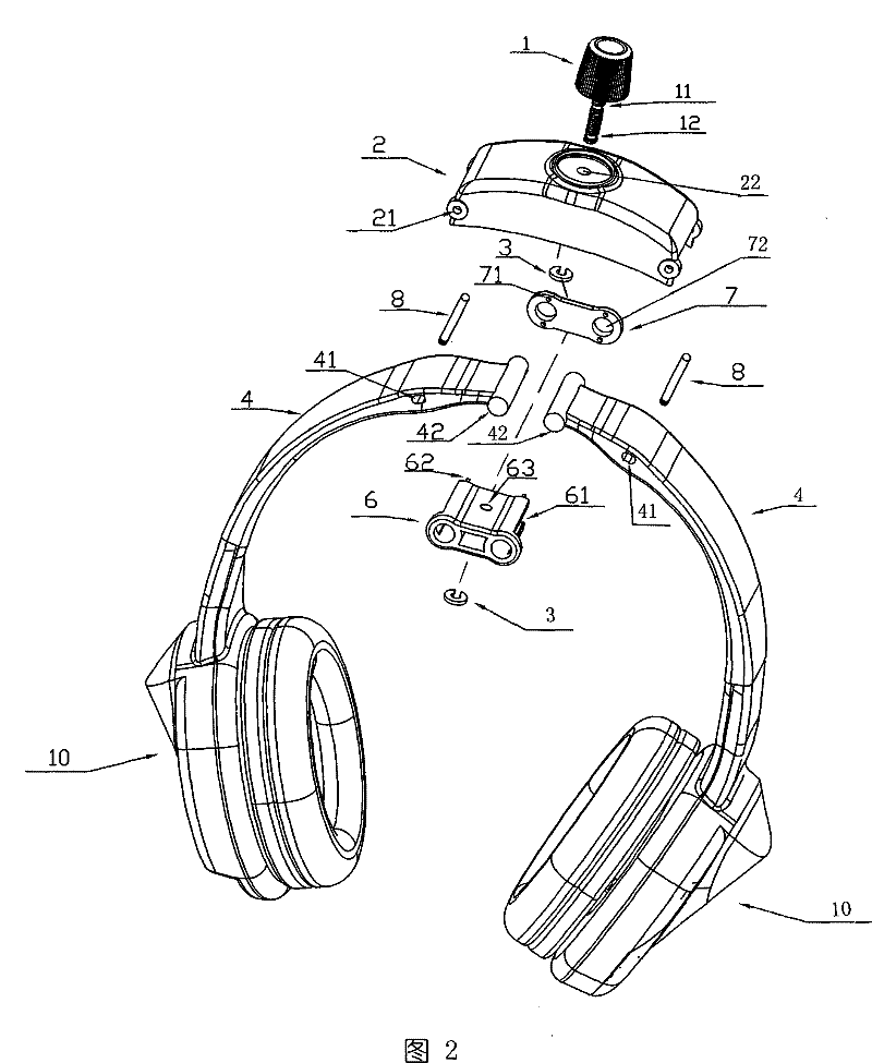
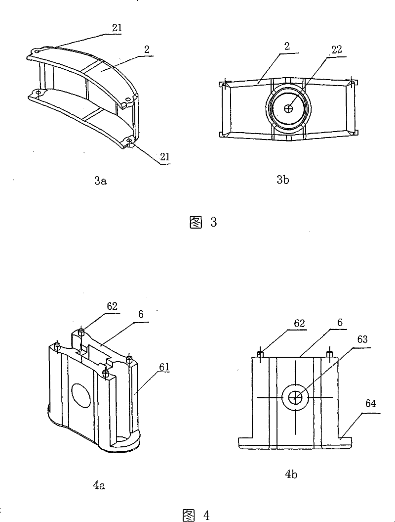
[0022] Such as Figure 1 to Figure 7 The earphone microphone with adjustable clamping force shown has left and right earphones 10, left and right connecting rods 4 connected to each other with the left and right earphones, the ends of the connecting rods 4 are fixed with pin shafts 42, and the length of the pin shafts is slightly Longer than the width of the connecting rod 4, the connecting rod has a radially arranged oval hole 41 near the front end. There are connecting rod holders 6 at the ends of the left and right connecting rods 4, see Figure 4 as shown, Figure 4 a is a perspective view of the connecting rod fixing seat 6, Figure 4 b is the main view. The left and right ends of the connecting rod holder are provided with split pin holes 61 that cooperate with the pin shaft 42 and can make the left and right connecting rods connected to the pin shaft rotate to a certain extent. The diameter of the hole, and the possibility that the left and right connecting rods con...


PUM


Abstract

The invention discloses an earphone microphone the clamping force of which is adjustable. The earphone microphone is provided with earphones and a connecting rod connected with the earphones; the connecting rod connected with the earphones is divided into a left part and a right part; the left part is hinged with the right part; a clamping force adjusting mechanism is arranged in the middle of the connecting rod; the clamping force adjusting mechanism comprises a supporting frame, a connecting rod fixing seat and an adjusting screw rod, wherein the supporting frame is articulated with the left connecting rod and the right connecting rod; the connecting rod fixing seat is hinged with the ends of the left connecting rod and the right connecting rod; the adjusting screw rod is positioned between the supporting frame and the connecting rod fixing seat, and used for adjusting the distance between the supporting frame and the connecting rod fixing seat. Because the adjusting mechanism whichcan adjust the opening between the left earphone and the right earphone is arranged on the connecting rod between the two earphones, the purpose of adjusting the clamping force between the two earphones is achieved; furthermore, the earphone microphone has the advantages of simple structure, convenient use and comfortable wear.

Description

technical field [0001] The invention relates to an earphone, in particular to an earphone with adjustable clamping force or an earphone with a microphone. Background technique [0002] Headphones usually use the connecting rod between the left and right earphones, such as: the elastic force of the plastic or metal strip is used as the clamping force of the earphone to clamp the ear. In order to make the earphone can be reliably clamped, production or The design unit often uses a larger clamping force than the actual need to clamp. Due to the excessive clamping force, the size of the force cannot be effectively adjusted. Therefore, when the earphone is used for a long time, it will be damaged due to excessive clamping force. It causes ear pain and headache and brain swelling, which not only affects the health of the body, but also sharply reduces the joyful mood. Contents of the invention [0003] The main purpose of the present invention is to overcome the above disadv...

Claims


Application Information

Patent Timeline
Patent Type & Authority Patents(China)
IPC IPC(8): H04R1/10H04R1/08
Inventor 沙静明
Owner NINGBO EXCEL ELECTRONICS
Learn More