
Heat shield

A technology for heat shields and components, applied in the direction of mufflers, exhaust treatment, engine components, etc.

Inactive Publication Date: 2008-12-24
FEDERAL MOGUL SEALING SYST
View PDF1 Cites 7 Cited by
  • Summary
  • Abstract
  • Description
  • Claims
  • Application Information

AI Technical Summary

Problems solved by technology

[0005] However, depending on the complexity of the structure to be shielded, it is not always possible to provide a one-piece heat shield

Method used


Image

  • Heat shield
  • Heat shield

Examples


Embodiment Construction

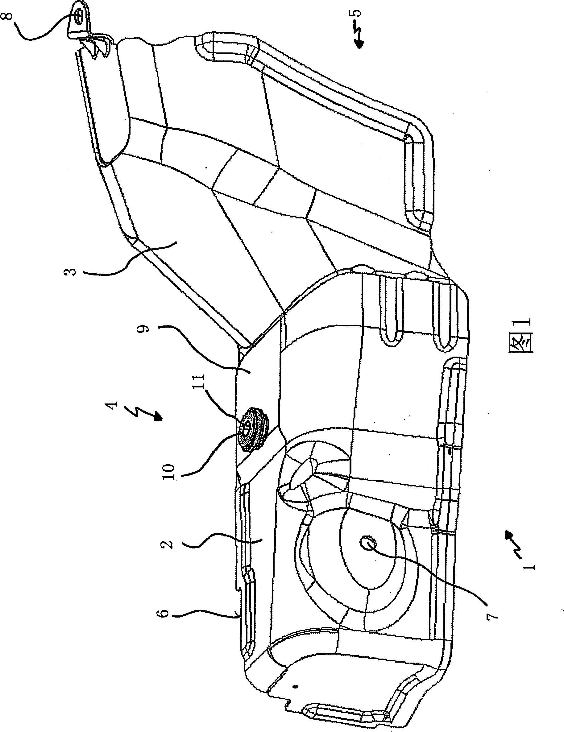
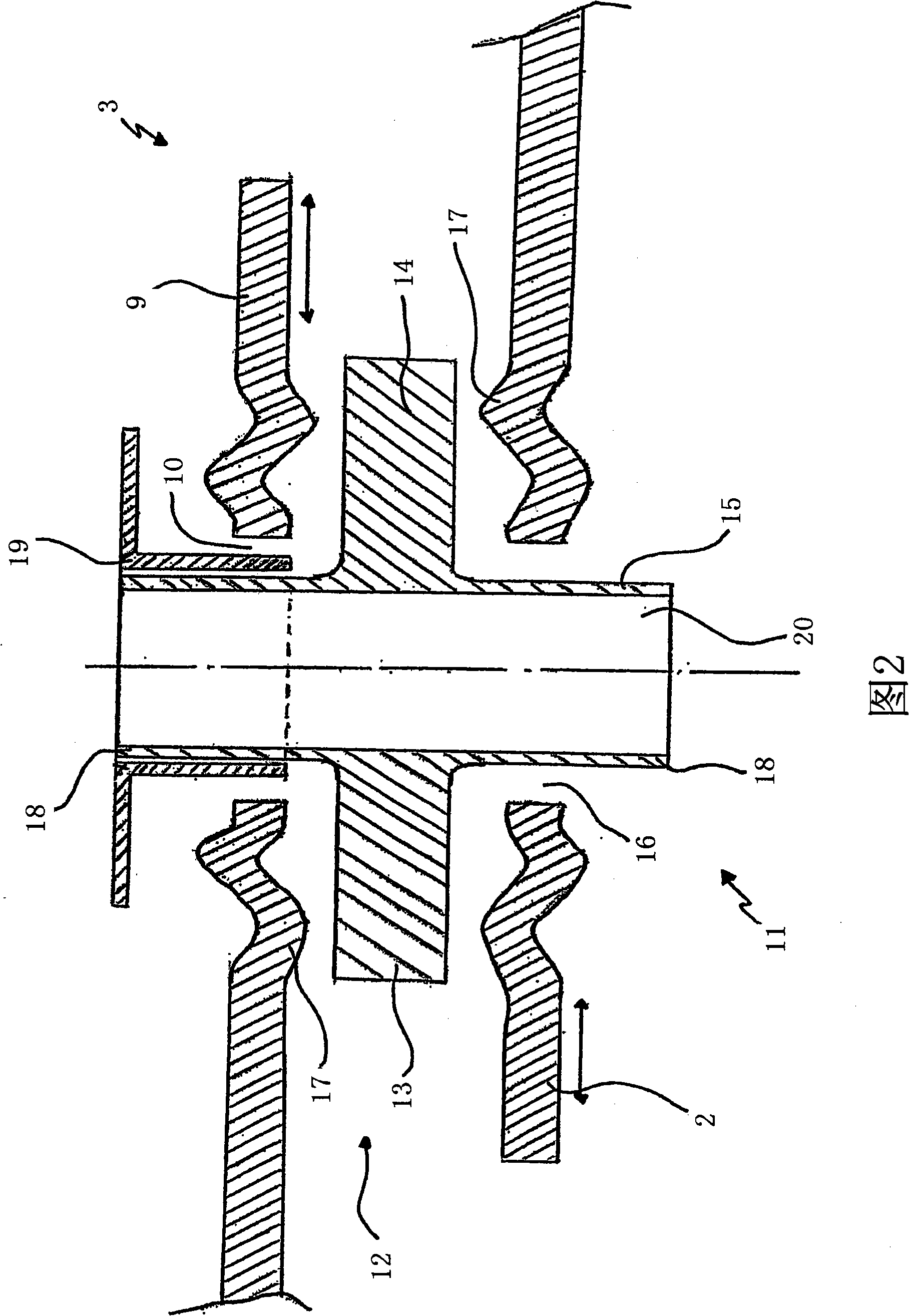
[0025] FIG. 1 shows a perspective view of a heat shield 1 which is intended to consist of two parts 2 , 3 in this exemplary embodiment. In this exemplary embodiment, the heat shield 1 also shields the exhaust manifold 4 , which is only schematically visible here. The exhaust manifold is a part of the exhaust system which can include, for example, an exhaust supercharger in the region 5 . It can be seen that the engine side of the exhaust manifold 4 has a connection region 6 which comprises a spatially complex structure in the direction of the region 5 . The individual components 2 , 3 are therefore also designed differently depending on the contour, that is to say they are approximately adapted to the spatial configuration of the exhaust manifold 4 . Part 2 has fastening regions 7 on exhaust manifold 4 , and part 3 has fastening regions 8 on exhaust gas supercharger 5 , by means of which they are fixedly movable relative to the structural part in question. Different temperat...


PUM


Abstract

The invention relates to a heat shield (1), composed of a plurality of elements, for shielding temperature-sensitive components, formed by elements which are substantially matched to the respective contour of the component which is to be shielded and which at least partially overlap one another, wherein the elements (2, 3) are provided so as to be fixed at least in a punctiform manner but moveable relative to one another in the overlapping region.

Description

technical field [0001] The invention relates to a heat shield composed of several parts for shielding structural elements under the influence of temperature. Background technique [0002] It is generally known to use heat shields for shielding structural components exposed to temperature influences, such as, for example, the exhaust manifold of a motor vehicle or the like. The thermal expansion of the structural parts respectively exposed to the influence of temperature can lead to detachment of the solidly connected heat shields used here, which are usually constructed in one piece. In particular, the exhaust manifold can expand by up to 5 mm under the influence of temperature. Tensions on the heat shield are thus implied in the fastening region of the heat shield, which tensions can lead to crack formation due to additional vibrations in the exhaust gas line. [0003] Here, decoupling elements are used as necessary in order to take into account the above-mentioned detach...

Claims


Application Information

Patent Timeline
Patent Type & Authority Applications(China)
IPC IPC(8): F01N7/14F02B77/11B60R13/08F01N7/10F01N13/14F01N13/10
CPCB60R13/0876F01N13/10F01N13/14F01N2260/20B60R13/08F02B77/11
Inventor 安德烈亚斯·斯皮尔
Owner FEDERAL MOGUL SEALING SYST
Learn More